SR200
Specifications subject to change
2.5
in the holder. It is advisable to connect the lead to the display-traverse unit first and then the
pick-up. To connect the pick-up to the display-traverse unit: the pick-up has 2 threaded ends
with location pins. Insert the location pin securely into the SR200 body and tighten the threaded
collar.
When the extension rod is used, the short pick-up lead is not required and the end of the rod
itself is inserted into the holder.
Pick-up:
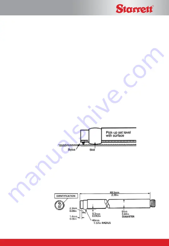
The pick-up is a variable inductive type transducer, which is supported on the
surface to be measured by a skid, a curved support projecting from the underside of the pick-
up in the vicinity of the stylus. As the pick-up traverses across the surface, movements of the
stylus relative to the skid are detected and con-verted into a proportional electrical signal. The
radius of curvature of the skid is much greater than the roughness spacing. This enables it to
ride across the surface almost unaffected by the roughness, and provide a datum representing
the general form of the surface. Even so, where the waviness is widely spaced it will be
necessary to use the pick-up with shoe, in conjunction with the 2.5mm (0.1in) cut-off.
Figure 5: the pickup is supported on the workpiece by the skid
There are several different types of pickup available designed for different applications, details
are given in the Accessories section of this handbook. They differ only in the stylus tip radius,
the dimensions of the housing or position and the shape of the skid. The stylus material in all
the pickups is diamond for low wear. The skids of the standard pickups are of red ruby.
Figure 6. Standard pick-up dimensions
Rapp Industrial Sales 724 789-7853


