STAR
TRAC
E-TBT
TOTAL
BODY
TRAINER
OWNER’S
MANUAL
9
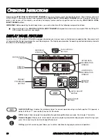
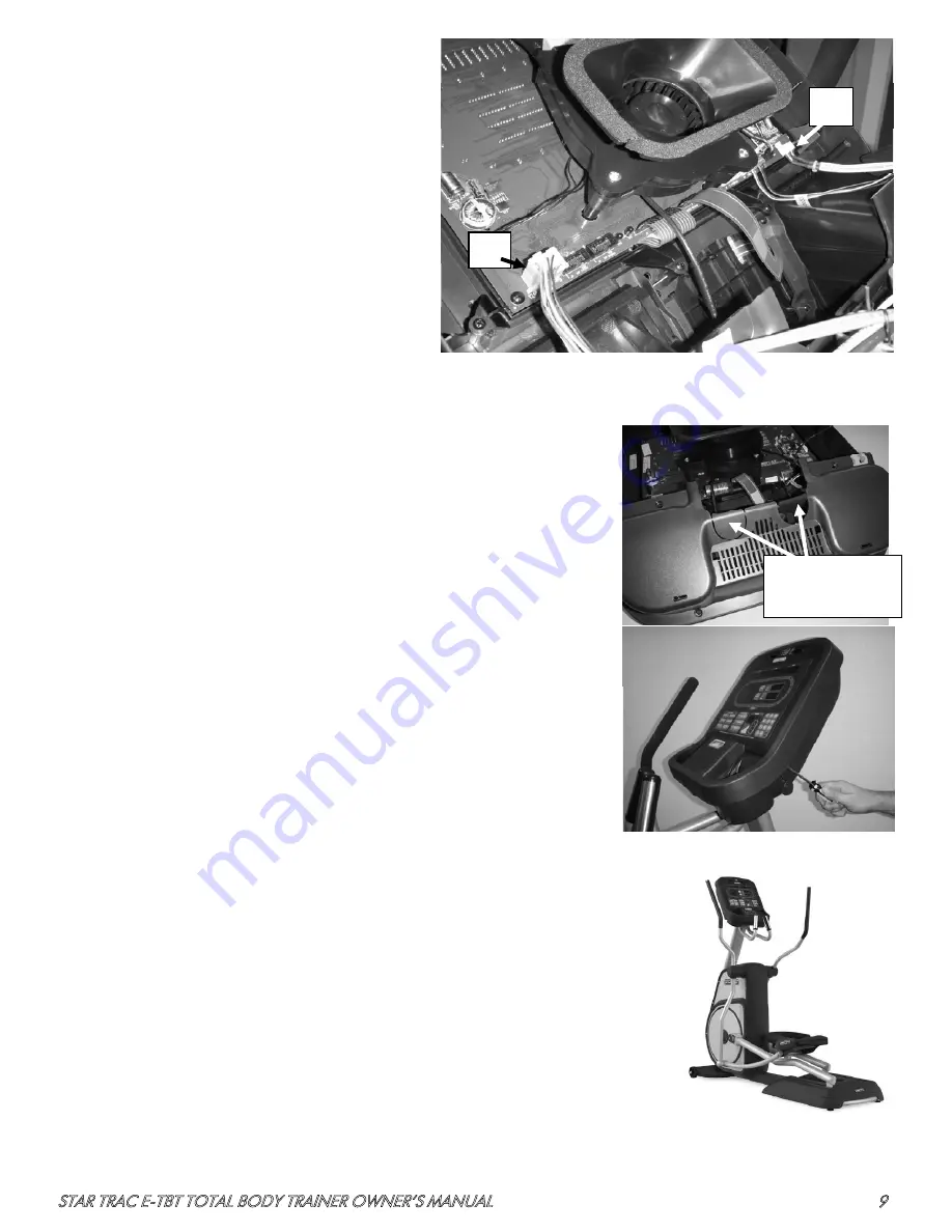
6. Connecting the Display Assembly
Note: This step assumes that you are connecting an
LED display assembly.
The following display connections will need to be made.
A. Connect the main display cable with a white 9 pin
connector to the J4 connector on the display PCB.
B. Connect the contact heart rate cable to the heart
rate board
C. Ground wire from the heart rate board must be
connected to the quick disconnect tab on the
display weldment (the location of the quick
disconnect tab is shown in Step 5.)
7. Final Display Assembly
With the electrical connections made you can now attach the display. For the TBT console
you will need to first remove the two plastic tabs from the bottom of the display console.
Simply flex the plastic back and forth several times and the tabs will break off or carefully
remove with cutters.
Next you will need to attach the front of the display to the weldment. First guide the bottom
of the display under the front tabs of the weldment and then second you will need to pivot
the display forward around the tabs to mate front display plastic to the rear plastic that is
attached to the weldment.
Once in place attach the plastics with the M4 screws included with the display. There are 8
M4 screws that attach around the perimeter of the display.
8. Final Setup
Be sure all bolts and screws are tightened securely.
Operate the unit to check for proper operation. The LED display should power up after
the first few strides and the console should turn on.
Move the unit to its final place of operation and check to see if the unit is level. If
needed, use the four leveling feet to properly level the unit. To do this, loosen the lock
nuts on the adjusters. Rotate the adjusters until the unit is stabilized, then retighten the
lock nuts.
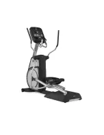
You have now completed the assembly of your Star Trac E-TBT Total Body Trainer.
A
B
Step 6
Remove Tabs
Step 7


