FLUE LINERS
Chimneys lined with salt glazed earthenware pipes
are acceptable if the pipes comply with B.S. 1181
and must be 125mm (5”) diameter. When using an
existing chimney, a liner approved to B.S. 4543 Part
1,2,3 should be used. The liner should be secured
at the top and bottom using closure clamping plates
firmly sealed and secured, and an approved termi-
nal used at the top. See Fig. 8.
It is essential that every flue system be inspected
and tested by the installer, to ensure that all the
combustion products are completely discharged to
the outside atmosphere.
Blank off the entrance and exit of the chimney
around the flue liner, trapped air will help to insulate
the flue. With a chimney system where it is not pos-
sible to trap air then it is best to back fill with an
approved insulating material.
9
FLUE MATERIALS
Salt glazed earthenware flue and purposely made
pre-cast sealed concrete chimneys or a rigid or flex-
ible stainless steel liners suitable for oil firing.
SEALING
As the stove operates under negative pressure it is
essential that all flue joints are tightly sealed against
flue gas leakage.
FLUE HEIGHT
The flue must be high enough (3 .35 meters / 11 ft.
min) to allow the flue gases to vent into the clear air.
It must be away from turbulence that may be caused
by roof structures, other chimney stacks etc.. The
venting position should be 1 meter (3’ 3”) above any
obstruction within a 600mm (24”) radius of the vent
termination. (Refer to Building Regulations).
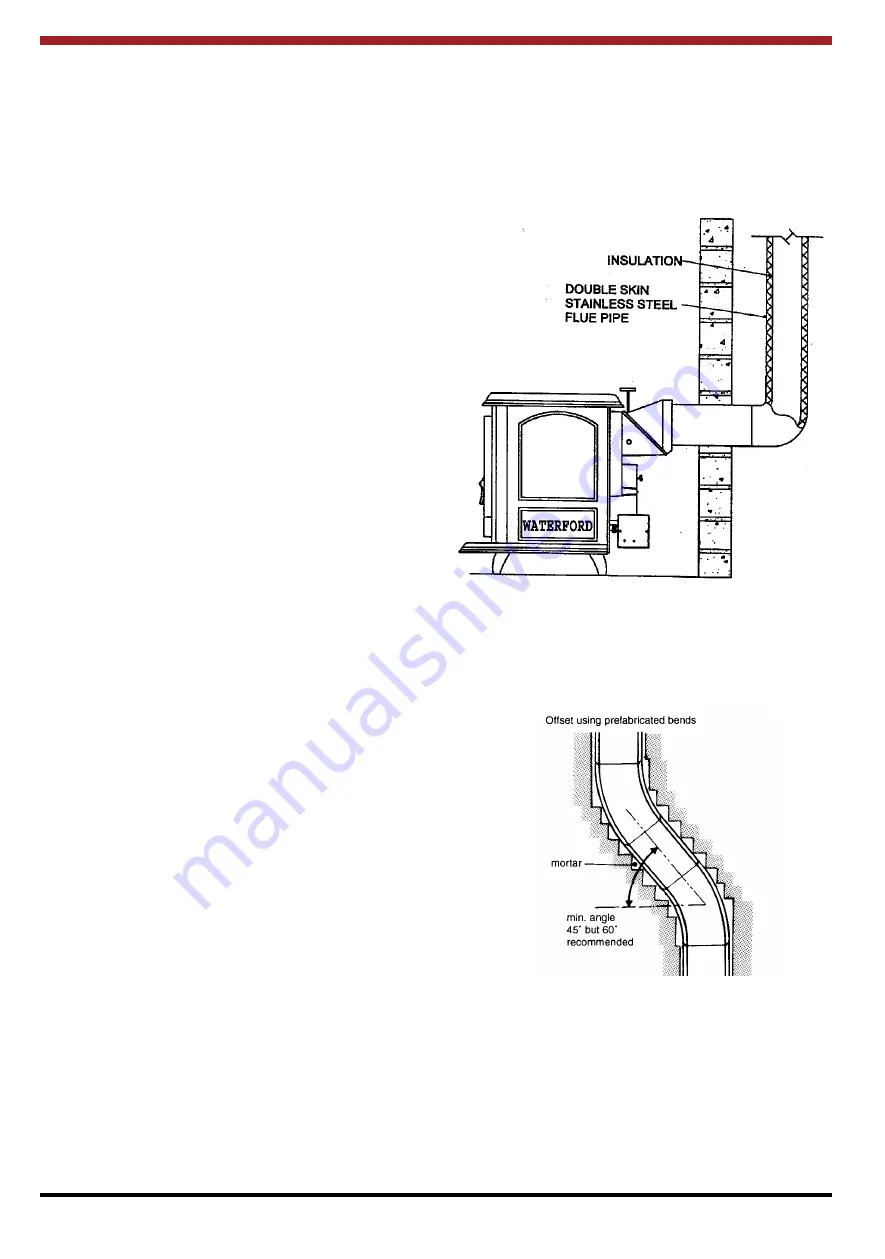
Where a standard lined masonry chimney is not
available, a proprietary type of non-combustible or
non-corrosive 125mm (5”) twin wall fully insulated
pipe may be used. The pipe must terminate at roof
point not lower than the main ridge or adjacent struc-
tures. With such installation, access to the chimney
must be provided for cleaning purposes.(See Fig. 9)
If it is necessary to offset the chimney the recom-
mended angle is 60
o
to the horizontal and the statu-
tory minimum is 45
o
. (See Fig. 10).
FACTORY MADE INSULATED CHIMNEYS
Factory made insulated chimney systems should be
constructed and tested to meet the relevant stan-
dards and recommendations given in B.S. 7566,
B.S. 4543 and any other current regulation or local
requirements having jurisdiction
Fig. 9
CONNECTIONS
Horizontal runs more than 300mm (12”) and 90
o
bends numbering more than 2 per installation should
be avoided.
Fig.10
DRAUGHT REQUIREMENTS
The Oisin Oil Stove requires a steady draught of :
0.03” w.g. - 0.06” w.g.
(0.75mm w.g. - 1.5mm w.g.)
Installations which are prone to down draughts
should be fitted with an anti-down draught cowl. For
correct flue installation, refer to Flue Section in this
manual.
Содержание Oisin Oil MK II
Страница 18: ...19 WIRING DIAGRAM Fig 47...


