


G
B
26
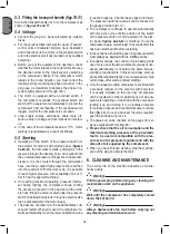
5.3
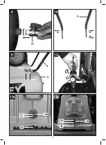
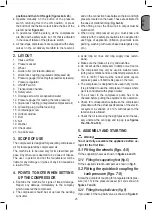
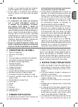
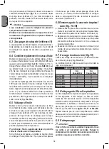
Fitting the transport handle (figs.10-11)
Screw the transport handle (ref. 9) to the compressor as
shown in
figures 10 and 11
.
5.4 Voltage
● Connect the plug to a panel protected by suitable
fuses.
● For the versions fitted with electric panel (“Tandem”
control units or delta/star starters) have installation
and connections (to the motor, to the pressure switch
and to the electrovalve if any) carried out by qualified
personnel.
● Before you put the equipment into operation, check
whether the motor rotates in the correct direction (see
the direction arrow on the V-belt cover) by switching
on the compressor briefly. If the compressor motor
rotates in the wrong direction, you must correct the
rotating field by reversing the phase converter in the
plug (use a screwdriver to depress the phase con-
verter slightly and turn it through 180°).
●
The motor is equipped with an overload switch. If
the compressor overloads, the overload switch will
switch off the equipment automatically to protect the
compressor from overheating. If the overload switch
triggers, wait for the compressor to cool down.
●
Long supply cables, extensions, cable reels etc.
cause a drop in voltage and can impede motor start-
up.
●
In the case of low temperatures below +5°C, motor
start-up is jeopardized as a result of stiffness.
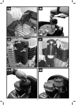
5.5 Starting
●
Operating on the switch of the pressure switch (or
the selector for versions with electric panel, (
figures
2a-2b-2c
), the compressor starts, pumping air in the
reservoir through the delivery hose. Air is sucked into
the so-called low pressure cylinder liner and precom-
pressed. It is then routed, through the recirculation
hose, into the so-called high pressure liner and then
into the reservoir. With this work cycle, it is possible
to reach higher pressure, with availability of air at 11
bar (15 bar for special machines).
●
On reaching maximum operating pressure (factory-
set during testing), the compressor stops, venting
the excess air present in the head and in the deliv
-
ery hose through a valve located under the pressure
switch (in delta/star versions, through an electrovalve
that is activated when the motor stops).
●
The absence of pressure in the head facilitates sub-
sequent restart. When air is used, the compressor re-
starts automatically when the lower calibration value
is reached (approx. 2 bar between upper and lower).
The pressure inside the reservoir can be checked on
the gauge provided (ref. 12).
●
The compressor continues to operate automatically
with this work cycle until the position of the switch
of the pressure switch (or of the selector of the elec-
tric panel,
figures 2a-2b-2c
) is modified. To use the
compressor again, wait at least 10 seconds after this
has been switched off before restarting.
●
In the versions with electric panel, the pressure switch
must always be aligned with the
I
(
ON
) position.
●
In tandem versions, the control unit provided permits
use of only one of the two compressor groups (if nec-
essary alternatively) or of both at the same time ac-
cording to requirements. In this second case, start-up
will be differentiated slightly to avoid excessively high
current take-off at start-up (timed starting).
●
Only the wheel-mounted compressors are fitted with
a pressure reducer (in the versions with fixed feet,
it is usually installed on the use line). Air pressure
can be regulated in order to optimize use of air-pow-
ered tools operating on the knob with the valve open
(pulling it up and turning it in a clockwise direction
to increase pressure and counterclockwise to reduce
this) (
fig. 12
). Once you have set the value required,
push the knob down to lock it.
●
The value set can be checked on the gauge (for ver-
sions equipped with this,
fig. 12
).
●
Please check that the air consumption and the
maximum working pressure of the pneumatic
tool to be used are compatible with the pres-
sure set on the pressure regulator and with the
amount of air supplied by the compressor.
●
When you have finished working, stop the machine,
pull out the plug and empty the tank.
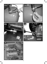
6. CLEANING AND MAINTENANCE
The service life of the machine depends on mainte-
nance quality.
Warning!
Pull the power plug before doing any cleaning and
maintenance work on the appliance.
Warning!
Wait until the compressor has completely cooled
down. Risk of burns!
Warning!
Always depressurize the tank before carrying out
any cleaning and maintenance work.
Содержание BA 1100/11/500 (M)
Страница 10: ...10 2b 2c 2a ON OFF ON 3a 2d OFF ON 3b...
Страница 11: ...11 7 2 8 6 5 17 19 4 4 19 18 18 13 13 2 2 2 3 18 17 4a 4b 3...
Страница 12: ...12 10 9 11 9 2 12 9 21 13a 15 min max 16 13b 15 min max 16...
Страница 13: ...13 14a 14b 17 A A 15 11 16 18 1 2 cm...
Страница 14: ...14 19a 20 19b 21 22a 22b...
Страница 15: ...15 23a 23b 25 24a 24b...
Страница 16: ...16...
Страница 84: ...84 G R 1 5 C 40 C 4 5 50 cm S3 50 5 5...
Страница 89: ...89 G R 2d 2a 2b 2c 25...
Страница 129: ...129 R U 1 5 C 40 C 4 5 50...
Страница 130: ...130 R U 2 1 2 3 4 5 6 7 8 9 10 11 12 13 14 15 16 17 18 19 20 21 3 4 S3 50 5 5 2a 2b 2d 10 3a 3b...
Страница 132: ...132 R U 2 12 2a 2b 2c I ON Tandem 12 12 6 6 1 6 2 15 11...
Страница 134: ...134 R U M6 9 11 M8 22 27 M10 45 55 M12 76 93 M14 121 148 6 8 100 20 21 22a 22b 3 6 9 7 8 23 24 20 21 22a 22b 18...
Страница 135: ...135 R U 2d 2a 2b 2c 25...
Страница 154: ...154 B G 1 5 C 40 C 4 5 50...
Страница 155: ...B G 155 S3 50 5 5 2a 2b 2d 10 3a 3b 2 1 2 3 4 5 6 7 8 9 10 11 12 13 14 15 16 17 18 19 20 21 3 4 E 5 C 40...
Страница 157: ...B G 157 100 100 300 2a 2b 2c 10 I ON 12 12 6 6 1 6 2 15 11...
Страница 159: ...B G 159 8 23 24 C C 20 21 22a 22b 18...
Страница 160: ...160 B G 2d 2a 2b 2c 25...
Страница 185: ...185 memo...
Страница 186: ...186 memo...
Страница 187: ...187 memo...


