


G
B
25
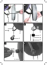
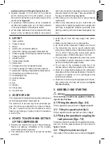
position and then to ON again
(
figures 2a & 2b
).
●
Operate manually on the button of the pressure
switch, returning this to the ON position, or press
the button of the thermal cutout inside the box of the
electric panel (
figure 2d
).
●
To guarantee machine safety, all the compressors
are fitted with a safety valve (ref. 10) that is activated
in the case of failure of the pressure switch.
●
All two-stage compressors are equipped with safety
valves on the air delivery manifold to the reservoir
and on the connection hose between the low and high
pressure located on the head. These are activated in
the case of malfunctioning (
fig. 3a-3b
).
●
When fitting a tool, the flow of air in output must be
switched off.
●
When using compressed air, you must know and
comply with the safety precautions to be adopted for
each type of application (inflation, pneumatic tools,
painting, washing with water-based detergents only,
etc.).
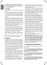
2. LAYOUT
1. Intake air filter
2. Pressure vessel
3. Wheel
4. Guide roller (or vibration-damper)
5. Quick-lock coupling (regulated compressed air)
6. Pressure gauge (for reading the preset tank pressure)
7. Pressure regulator
8. ON/OFF switch
9. Transportation handle
10. Safety valve
11. Drainage screw for condensation water
12. Pressure gauge (for reading the tank pressure)
13. Quick-lock coupling (unregulated compressed air)
14. Oil sealing plug (oil filler opening)
15. Oil drainage screw
16. Oil level window
17. Bolt
18. Nut
19. Washer
20. Check valve
21. Tap ball valve
3. SCOPE OF USE
The compressor is designed for generating compressed
air for tools operated by compressed air.
The machine is to be used only for its prescribed pur-
pose. Any other use is deemed to be a case of misuse.
The user / operator and not the manufacturer will be
liable for any damage or injuries of any kind caused as
a result of this.
4. POINTS TO NOTE WHEN SETTING
UP THE COMPRESSOR
●
Examine the machine for signs of transit damage.
Report any damage immediately to the company
which delivered the compressor.
●
The compressor should be set up near the working
consumer.
●
Avoid long air lines and long supply lines (exten-
sions).
●
Make sure the intake air is dry and dust-free.
●
Do not set up the compressor in damp or wet rooms.
●
The compressor may only be used in suitable rooms
(with good ventilation and an ambient temperature from
+5°C to +40°C). There must be no dust, acids, vapors,
explosive gases or inflammable gases in the room.
●
The compressor is designed to be used in dry rooms.
It is prohibited to use the compressor in areas where
work is conducted with sprayed water.
●
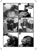
The oil level in the compressor pump has to be
checked before putting the equipment into operation.
●
Check for correspondence between the compressor
plate data with the actual specifications of the electri-
cal system. A variation of ± 10% with respect of the
rated value is allowed.
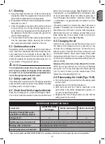
●
Check the oil level using the sight glass and if neces
-
sary unscrew the vent plug and top up (see
figures
13a-13b-14a-14b
).
5. ASSEMBLY AND STARTING
Warning!
You must fully assemble the appliance before us-
ing it for the first time.
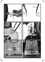
5.1 Fitting the wheels
(figs. 4
-
5)
Fit the supplied wheels as shown in
figures 4 and 5
.
5.1.1 Fitting the supporting feet (fig. 6)
Fit the supplied vibration-dampers as shown in
fig. 6
.
5.2 Fitting the quick-lock coupling for
tank pressure (figs. 7-8)
Screw the quick-lock coupling for unregulated tank pres-
sure (ref. 13) to the pressure vessel (ref. 2) as shown in
figures 7 and 8
.
5.2.1 Fitting the tap ball valve (fig. 9)
If provided, fit the tap ball valve as shown in
figure 9
.
Содержание BA 1100/11/500 (M)
Страница 10: ...10 2b 2c 2a ON OFF ON 3a 2d OFF ON 3b...
Страница 11: ...11 7 2 8 6 5 17 19 4 4 19 18 18 13 13 2 2 2 3 18 17 4a 4b 3...
Страница 12: ...12 10 9 11 9 2 12 9 21 13a 15 min max 16 13b 15 min max 16...
Страница 13: ...13 14a 14b 17 A A 15 11 16 18 1 2 cm...
Страница 14: ...14 19a 20 19b 21 22a 22b...
Страница 15: ...15 23a 23b 25 24a 24b...
Страница 16: ...16...
Страница 84: ...84 G R 1 5 C 40 C 4 5 50 cm S3 50 5 5...
Страница 89: ...89 G R 2d 2a 2b 2c 25...
Страница 129: ...129 R U 1 5 C 40 C 4 5 50...
Страница 130: ...130 R U 2 1 2 3 4 5 6 7 8 9 10 11 12 13 14 15 16 17 18 19 20 21 3 4 S3 50 5 5 2a 2b 2d 10 3a 3b...
Страница 132: ...132 R U 2 12 2a 2b 2c I ON Tandem 12 12 6 6 1 6 2 15 11...
Страница 134: ...134 R U M6 9 11 M8 22 27 M10 45 55 M12 76 93 M14 121 148 6 8 100 20 21 22a 22b 3 6 9 7 8 23 24 20 21 22a 22b 18...
Страница 135: ...135 R U 2d 2a 2b 2c 25...
Страница 154: ...154 B G 1 5 C 40 C 4 5 50...
Страница 155: ...B G 155 S3 50 5 5 2a 2b 2d 10 3a 3b 2 1 2 3 4 5 6 7 8 9 10 11 12 13 14 15 16 17 18 19 20 21 3 4 E 5 C 40...
Страница 157: ...B G 157 100 100 300 2a 2b 2c 10 I ON 12 12 6 6 1 6 2 15 11...
Страница 159: ...B G 159 8 23 24 C C 20 21 22a 22b 18...
Страница 160: ...160 B G 2d 2a 2b 2c 25...
Страница 185: ...185 memo...
Страница 186: ...186 memo...
Страница 187: ...187 memo...


