1 – 10
Getting Started
1.6
Interlock
The DC205 is designed with a safety interlock circuit that must
be definitively activated for the
±
100 V output range to be en-
abled. The interlock is intended to support safe operation of
WARNING
this instrument in a test system. Bypassing the interlock can
lead to a hazardous condition, possibly exposing the operator
to dangerous electrical potentials up to
±
100 V, capable of caus-
ing injury or death.
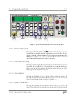
Figure 1.1: The DC205 rear panel, shown with an interlock defeat plug.
For safety, the
±
100 V range can only be enabled when the interlock
signal is asserted. To assert the interlock, a low impedance circuit
must be closed between pins 1 and 2 of the rear-panel INTERLOCK
socket. A mating plug is provided with the DC205.
When the interlock is asserted, the front panel
Interlock
indicator will
be illuminated. The interlock must be asserted to enable OUTPUT
On
when the RANGE is
±
100 V
.
Note that the
±
1 V
and
±
10 V
range settings can be enabled inde-
pendent of the whether the interlock is asserted.
DC205 Precision DC Voltage Source

