ASSEMBLY INSTRUCTIONS
8
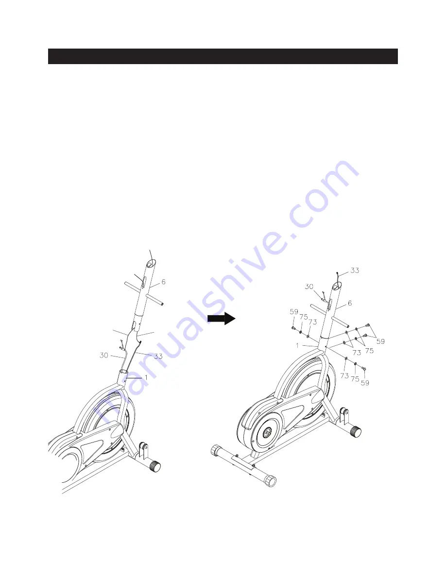
STEP 3
NOTE:
There is a red strap and a black strap attached inside of the
UPRIGHT(6).
These straps are to
assist in pulling the
SENSOR WIRE(33)
and
TENSION CABLE(30)
through the
UPRIGHT(6).
Tie the red strap to the plug end of the
SENSOR WIRE(33),
and tie the black strap to the cable end of
the
TENSION CABLE(30).
Pull the red strap from the opening at the top of the
UPRIGHT(6)
until the
SENSOR WIRE(33)
is pulled through and extends out the opening. Pull the black strap until the
TENSION
CABLE(30)
is pulled through and extends out of the square opening in the side of the
UPRIGHT(6)
as
shown in the below illustration. Insert the
UPRIGHT(6)
into the
MAIN FRAME(1)
and secure with
BUTTON
HEAD BOLTS(M8x1.25x20mm)(59), LOCK WASHERS(M8)(75),
and
ARC WASHERS(M8)(73). Do not
tighten the bolts until STEP 11.
NOTE:
Don’t remove the straps from the
SENSOR WIRE(33)
and
TENSION CABLE(30)
until instructed
to do so in later assembly steps.
Red Strap
Black Strap


