


ASSEMBLY INSTRUCTIONS
WARNING:
The CRANKS(37) require a special tool to remove once assembled. Read all of the
following ASSEMBLY INSTRUCTIONS before attaching the CRANKS(37).
11
Allen Wrench
Socket Wrench
C.
A.
B.
White Mark
Arrow Mark
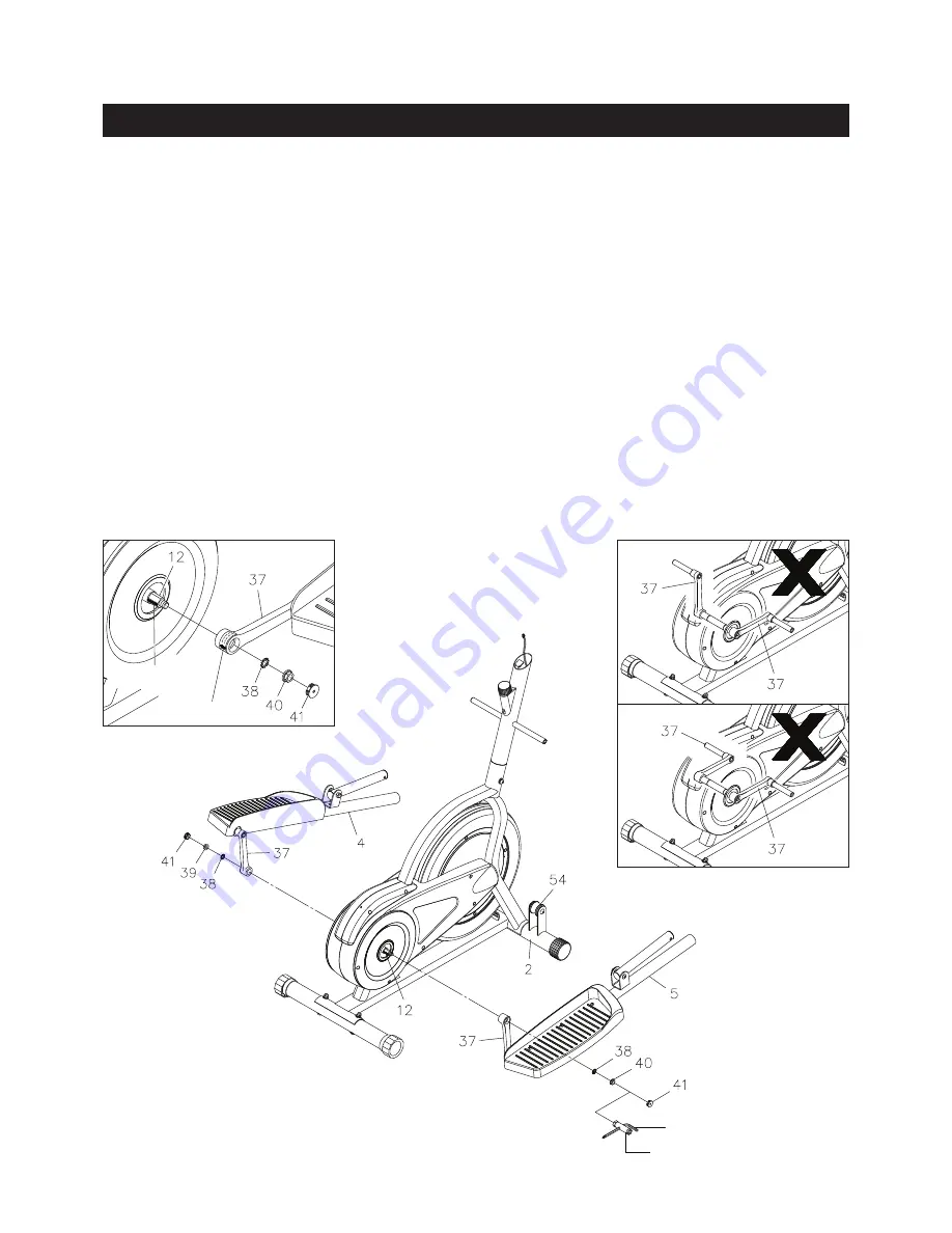
STEP 8
Place the front end of the
RIGHT PEDAL ARM(5)
on the
ROLLER(54)
of the
FRONT STABILIZER(2).
Install the
CRANK(37)
onto the
AXLE(12)
with
TOOTH LOCK WASHER(M8)(38)
and
RIGHT FLANGE
NUT(M10x1.25)(40).
Insert an allen wrench through the hole in the socket wrench to be the handle.
SECURELY TIGHTEN
the
RIGHT FLANGE NUT(M10x1.25)(40)
with the socket wrench. Push the
CRANK
CAP(41)
into the
CRANK(37).
1.
Align the ARROW MARK on the CRANK(37) to the WHITE MARK on the AXLE(12) when
installing the two CRANKS(37) onto the AXLE(12). Refer to inset drawing A.
2.
The
RIGHT FLANGE NUT(M10x1.25)(40),
black color, has right hand threads and is tightened
by turning clockwise. The
LEFT FLANGE NUT(M10x1.25)(39),
brass color, has left hand threads
and is tightened by turning counterclockwise.
NOTE:
CAUTION:
It is possible to assemble the
CRANKS(37)
the wrong way as shown in inset drawings
B
and
C.
The
CRANK(37)
on the
LEFT PEDAL ARM(4)
must be assembled in the opposite
direction from the right side. Refer to the below illustration. Use the same procedure as above
to assemble the
LEFT PEDAL ARM(4).


