background image

Technical Procedure

Page 6

620-8590  Rev. A

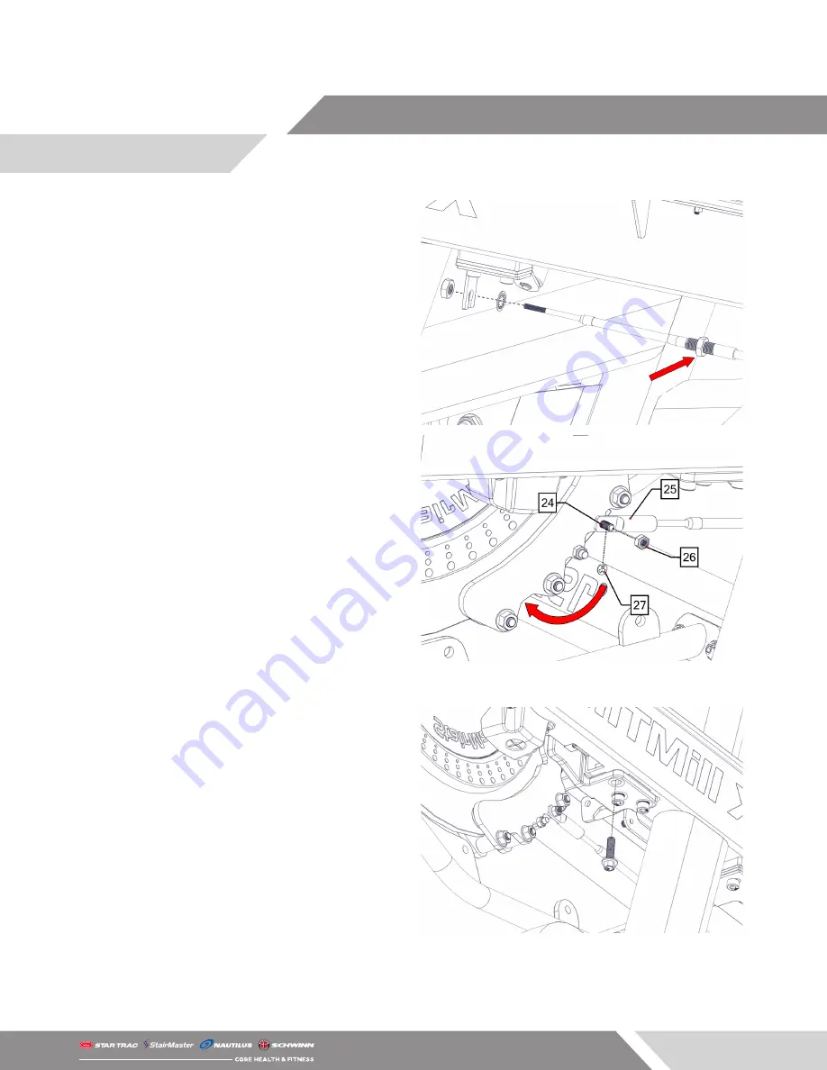
23.  Ensure that the bottom nut located on the cable 

is threaded all the way down then secure the 

bottom end of the new brake cable into the new 

cable bracket.

24.  Use a 5mm allen key and a 10mm wrench to re-

move and replace the brake screw with the screw 

supplied.

25.  Set the resistance to Level 6 then thread a cable 

fitting end onto the bottom of the cable and 

connect it to the left side of the brake via the 

screw installed in Step 24. Ensure that the brake 

is pushed up against the flywheel while attach-

ing the fitting to the brake screw.

26.  Using a 10mm wrench and a 5mm allen key, 

tighten the M6 nut onto the screw replaced in 

Step 24.

27.  Install the supplied e-clip onto the new brake 

screw.

28.   Remove 

ONE 

of the screws securing the brake 

assembly to the brake using a 6mm allen key, 

then use a 10mm socket to install one of the 

supplied hex head screws. DO NOT REMOVE ALL 

THREE SCREWS AT THE SAME TIME.

29.  Repeat Step 28 for the remaining two screws. All 

three screws should be replaced.

Содержание HIITMill

Страница 1: ...1 Remove the three 3 socket head cap screws se curing the brake covers to the unit using a 4mm allen key 2 Loosen the screw securing the brake cable to the brake then use a 10mm wrench to remove the M6 nut securing the brake cable to the cable bracket 3 Pull the entire cable from the back of the brake cable bracket HIITMill X Push Pull Brake Cable Install Applies to HIITMill and HIITMill X ...

Страница 2: ...n key to remove the two 2 M8 x 20mm screws from the user left side handrail 6 Use a 2 5mm allen key to remove the M4 x 8mm screw located in front of the M8 screws removed in Step 5 7 Repeat Steps 5 6 for the user right side hand rail 8 Once all the screws securing the handlebar to the frame have been removed remove the handle bar ...

Страница 3: ...hrough the frame while the level assembly is pulled from the top 11 Use a 5mm allen key to remove the two 2 M8 x 25mm screws securing the flywheel guard to the frame 12 Remove the three 3 M10 x 25mm screws secur ing the user left side handrail to the frame 13 Carefully separate the user left side handrail from the unit and lay the handrail on the deck WARNING Please be aware of any additional cabl...

Страница 4: ...Pull the push pull brake cable up through and out of the hole in the frame TECH TIP Use the supplied hook tool to grab the push pull brake cable and pull it up through the hole while feeing the brake cable from the bottom 16 Feed the new brake cable up through the user left side handrail ensuring that the cable routes BEHIND the weight horn and swing arm as shown 17 Reinstall the user left side ha...

Страница 5: ...d 7 16 toothed lock washer NOTE The amount of cable that is threaded into the fitting may need to be adjusted in order to attach the new resistance lever assembly See Step 19 20 Secure the cable fitting end to the resistance lever using the supplied clevis and cotter pin 21 Push the resistance lever assembly with attached cable back into the user left handrail be sure to pull any slack cable out o...

Страница 6: ...to the left side of the brake via the screw installed in Step 24 Ensure that the brake is pushed up against the flywheel while attach ing the fitting to the brake screw 26 Using a 10mm wrench and a 5mm allen key tighten the M6 nut onto the screw replaced in Step 24 27 Install the supplied e clip onto the new brake screw 28 Remove ONE of the screws securing the brake assembly to the brake using a 6...

Страница 7: ...hine 31 Test the tension on the new cable by pulling the lever all the way back to the STOP position the belt should not be moving while standing on the unit while the lever is in this postion If the belt does move refer to Step 25 as some adjustment may be needed 32 Install the new outer brake cover using a 4mm allen key and the three 3 screws removed in Step 1 ...

Отзывы: