Technical Procedure
Page 3
620-8590 Rev. A
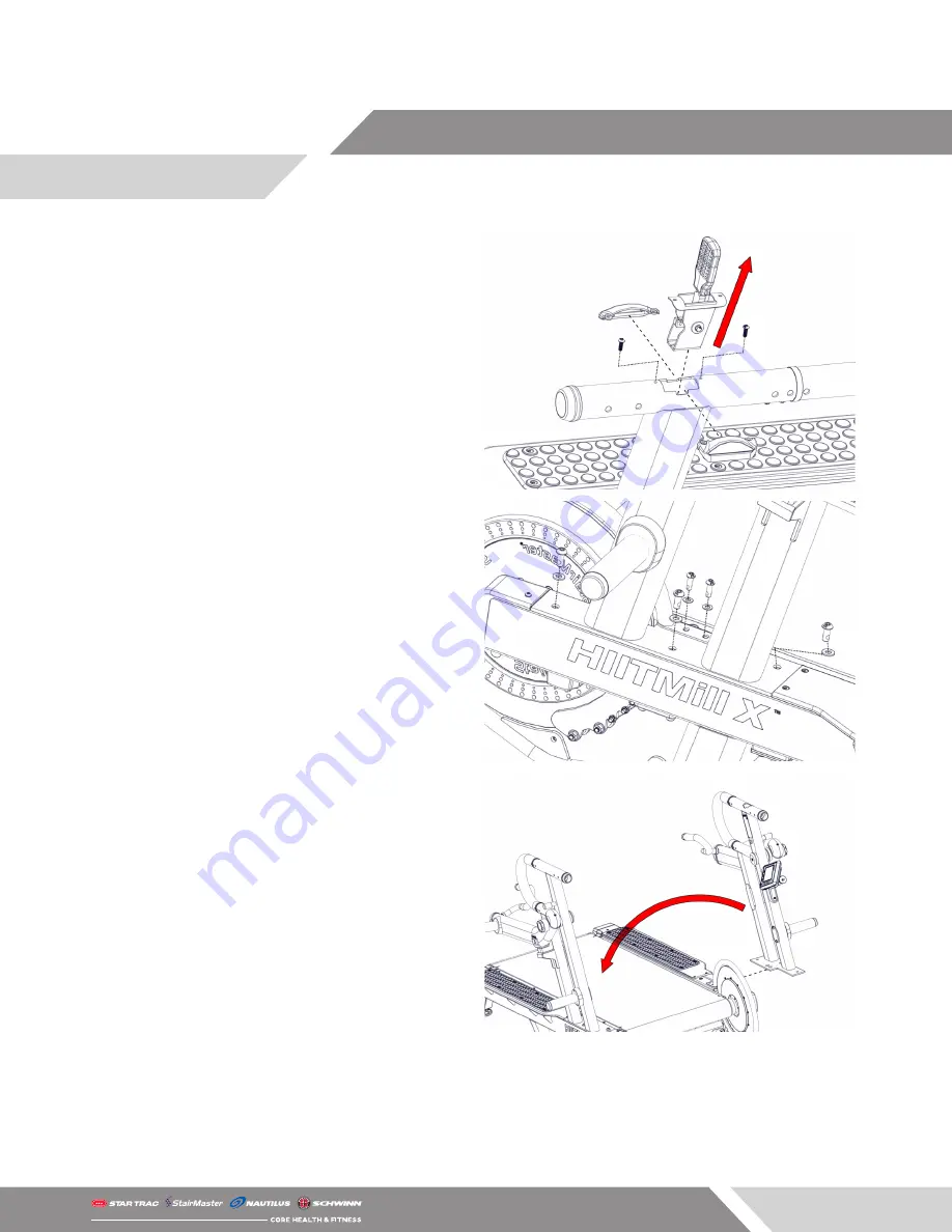
9. Use a 3mm allen key to remove the two (2) M5 x
16mm screws securing resistance lever covers to
the user left handrail.
10. Carefully pull up on the resistance lever to re-
move both the resistance lever assembly and the
brake cable.
NOTE: The brake cable may need to be fed up
through the frame while the level assembly is pulled
from the top.
11. Use a 5mm allen key to remove the two (2) M8 x
25mm screws securing the flywheel guard to the
frame.
12. Remove the three (3) M10 x 25mm screws secur-
ing the user left side handrail to the frame.
13. Carefully separate the user left side handrail from
the unit and lay the handrail on the deck.
WARNING
: Please be aware of any additional cables
running from the console to the brake. Ensure these
are not damaged or stretched during the removal of
the handrail.


