Page | 11
Wiring Installation
1. Switch off utility power to the distribution point where the UPS will be connected. Be
absolutely sure that there are no hazardous voltages present. Use lockout/tagout
procedures to assure safety.
2. Remove as many panels as needed for adequate access for wiring the cabinet. Open
the front door of the MBS Cabinet. If necessary, remove the top and bottom shield
cover panels located above and below the circuit breakers by removing the four (4)
screws that mount each in place. See
Figure 4
.
3. Connect wires from the "TO UPS INPUT" bus bar terminal pads, see
Figure 4
and
Figure 5
, to the input terminals in the UPS. (Refer to the UPS manual). The wire must
be in compliance with
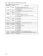
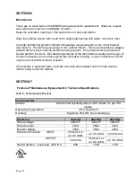
Table 3
and the terminals must be torqued in compliance with
Table 6
. Make sure that phase A connects to phase A and so on. If the bypass and
rectifier inputs are powered from separate sources, the bypass input must be fed from
the MBS.
4. Connect wires from the "FROM UPS OUTPUT" bus bar terminal pads to the output
terminals in the UPS. (Refer to the UPS manual). The wire must be in compliance with
Table 3
and the terminals must be torqued in compliance with
Table 6
. Make sure that
phase A connects to phase A and so on.
5. Connect wires from the "OUTPUT TO LOAD" bus bar terminal pads to the load. The
load may be an external distribution panel, etc. If neutral is not needed by the load,
then it does not need to be supplied. The wire must be in compliance with
Table 3
and
the terminals must be torqued in compliance with
Table 6
. Make sure that phase A
connects to phase A and so on.
6. A set of four or five control connections must be installed from the "CUSTOMER LOW
VOLTAGE CONNECTION TERMINAL BLOCK" to the Remote Commands and Alarm
Connections in the front of the UPS cabinet. These control wires must be physically
separated from any power wires. The length of the control wires is limited to 30 feet or
10 meters. These connections are described later in this section.
7. Verify that the input power source is not powered. Connect wires from the "UTILITY
INPUT" bus bar terminal pads to the input source power from the building distribution.
The wire must be in compliance with
Table 3
and the terminals must be torqued in
compliance with
Table 6
. Make sure that phase A connects to phase A and so on.
The source needs to have A-B-C phase sequence. If not, exchange two of the phase
connections to correct this.
8. If the system is the used in a wye-wye application, ensure that the neutral wires are
connected to the “Neutral” bus bar terminal pad.
9. Check all work. Replace the panels that were removed for access.
Insure that the
shield cover panels have been mounted in place. Failure to do so could subject
personnel to lethal voltages.


