P. 5
© 2004 Sportcraft, Ltd.
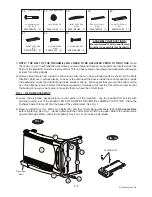
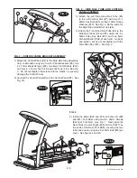
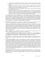
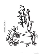
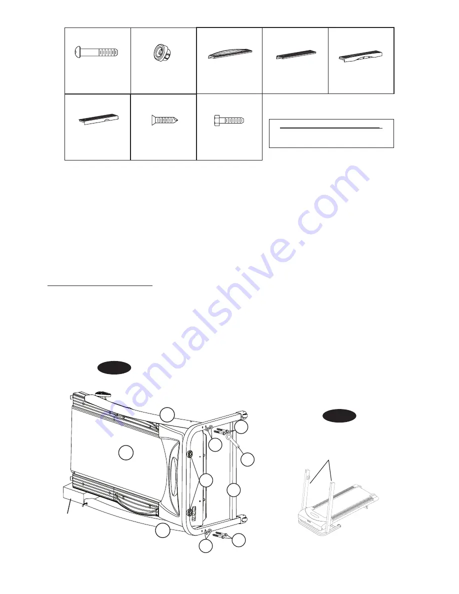
FIG. 1
FIG. 1A
32
32
9
13
9
10
11
7
6
1
36
37
38
42
41
40
39
43
04041BFH03 (2)
04041FH22 (1)
04041BFH04 (1)
04041BFH05 (1)
04041BFH06 (1)
04041BFH07 (1)
04045FH14 (8)
04041BFH08 (2)
Vertical Arm
Styrofoam
block
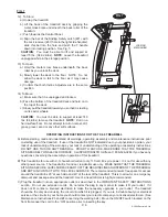
1)
NOTE: THE BELT OF THE TREADMILL WILL NEED TO BE ADJUSTED PRIOR TO FIRST USE.
Open
the carton of your new Treadmill near where you want it placed (Caution: some parts are located under the
frame of the treadmill). Select a clear level floor. This is a heavy piece of equipment and assembly will require
at least Two Strong Adults.
2) Remove all contents from inside the carton and verify that you have all listed parts as shown on the Parts
Identifier. Parts are in various places, so be sure to examine all the boxes, inside the control panel box, inside
the packaging, under the treadmill and inside smaller cartons. We suggest that you use the bottom carton
as a clean flat work area to protect the fitness equipment. Carefully cut or tear the four carton corners so that
the bottom is now your work area. Also verify that you have the correct tools.
FIG. 1: D-FRAME ASSEMBLY
3) Leave the styrofoam packing block on rear portion of the treadmill. Lay the treadmill on its side with
styrofoam at the rear of the treadmill. DO NOT ROTATE THE VERTICAL ARMS AT THIS TIME. Place the
D-shape Caster Frame (#10) at the base of the vertical arms. See Fig. 1.
4) Begin to install four 10 x 60mm Hex Bolts (#9) and four 10mm Spring Washers (#32)
at the same time
before tightening. See Fig. 1. Gently tighten with the 10mm Wrench (#13) provided. Rotate the vertical arms
upward (D-shape Frame under the treadmill). See Fig. 1A. Remove all styrofoam.
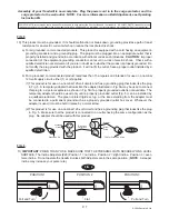
ASSEMBLY INSTRUCTIONS
:
We recommend that two adults work
together to assemble this treadmill.
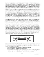
10 X 90MM ALLEN
KEY BOLT
LOCK RECEIVER
(PRE-INSTALLED)
(PRE-INSTALLED)
FRONT FOOT RAIL
- RIGHT
REAR FOOT RAIL
- RIGHT
FRONT FOOT RAIL
- LEFT
FRONT FOOT RAIL
- LEFT
6 X 25MM SCREW
- BLACK
6 X 20MM HEX BOLT


