background image

Initial Installation

Management Port Configuration

Spirent Landslide Test System Installation Guide 

|

27

14

The user will be prompted to configure the alternate IPv4 Address mode for any 
desired services that may require the use of IPv4. For example, if IPv4 addresses were 
used in provisioning NTP or PTP in the steps above, configuration of the IPv4 
Address mode is required. If no alternate IPv4 management interface is desired or 
needed, press 

Enter

 to accept the default value 

none

 to skip this step. Otherwise, 

specify 

static

 or 

dynamic

 to continue with configuring an alternate IPv4 management 

address.

Configure <TAS / TS / TAS+TS> alternate IPv4 Address mode 
(none/static/dynamic) [none]:

If 

static

 is selected, answer the resulting configuration prompts.

Specify a unique IPv4 address for the alternate IPv4 management address then 
press 

Enter

 to continue.

<

port

> <

TAS / TS / TAS+TS

IPv4 Address []:


Specify the IPv4 network mask, then press 

Enter

 to continue.

<

port

> <

TAS / TS / TAS+TS

IPv4


Network Mask []:


Specify the address for the IPv4 gateway in your network, then press 

Enter

 to 

continue.
<

port

> <

TAS / TS / TAS+TS

IPv4 IP Gateway []:

The initial configuration is complete at this point. Type 

yes

 and press 

Enter

 to reboot 

the system.

System must be rebooted for these changes to take effect… 
Reboot now? (yes/no) [yes]:

Note:

If errors are detected in any of the data entered above, answer 

no

 to the reboot 

question and rerun the 

ipcfg

 command.

Содержание Landslide C100

Страница 1: ...P N 71 008573 REV A Installation Guide Spirent Landslide Test System October 2018 ...

Страница 2: ...an the Hardware Warranty Period or the Software Warranty Period as applicable Spirent does not warrant that the functions contained in the Software will meet a specific requirement or that the operation will be uninterrupted or error free Spirent shall have no warranty obligations whatsoever with respect to any Software which has been modified in any manner by Customer or any third party Defective...

Страница 3: ...ight trademark or confidentiality notices on the backup copies of the Software Software applications are licensed to specific serial number controllers or modules Upgrade versions of the Software may be used only on controllers or modules by serial number for which the original Software was purchased TERM This license is effective until terminated as set forth herein You may terminate this license...

Страница 4: ... agree to comply with the United States Export Administration Act of 1979 as amended and the United States Export Administration Regulations of the United States Department of Commerce with regard to the exportation of the Software and Documentation 3 This Agreement is the entire agreement between you and Spirent and supersedes any prior or contemporaneous agreements or communications oral or writ...

Страница 5: ...view 18 Landslide Manager Configuration 19 Landslide Test Server Configuration 19 Management Port Configuration 20 Chapter 3 Landslide E10 System Overview 29 Landslide E10 Test System 30 Deployment 30 System Configuration Overview 32 Federal Communication Commission Interference Statement 33 Chapter 4 Installing U1 OTA Modules on the Landslide E10 35 Introduction 36 Before You Begin 36 Package Con...

Страница 6: ...tem Installation Guide Installing the Tcl API 47 Securing the System 47 Default Passwords 47 Appendix A Landslide Test Server NIC Configurations 49 General 50 Supported NICs and IPSec Cards 50 Supported NIC Configurations and Port Names 52 ...

Страница 7: ...Spirent Landslide Test System Installation Guide 7 About this Guide In this chapter Introduction 8 Related Documentation 8 Shipment Contents 10 Release Notes 10 How to Contact Us 11 ...

Страница 8: ...can be found in the following related resources Refer to the latest version of the Landslide software Release Notes for the most current information regarding Landslide documentation These documents are provided in PDF format Spirent Landslide Test System Installation Guide this manual Landslide Test Server NIC Configurations appendix to this manual Landslide Virtual Machine Installation Instructi...

Страница 9: ...dslide E10 Stand alone Test System E10 TS Landslide E10 Test Server L C100 M4 TS Landslide C100 M4 Test Server L C100 S4 MGR Landslide C100 S4 Manager L C50 S4 SYS Landslide C50 S4 System Appliance L C50 S4 TS Landslide C50 S4 Add on Test Server Manager Test Administration Server Appliance SPT C100 M4 TS Same as L C100 M4 TS SUT System Under Test TAS Test Administration Server TS Test Server vTAS ...

Страница 10: ...l Test Server s For C50 Test Systems 1 Landslide C50 Test System appliance with power cord 0 or 1 Landslide C50 Add on Test Server only one stand alone Add on Test Server can be added to a C50 Test System EDGE E10 System Check your system to ensure that you have the following items 1 Landslide EDGE E10 appliance 1 Power supply and cord 3 Dual band 2 4 and 5 8GHz antennas 1 Ethernet cable Release N...

Страница 11: ...one 1 818 676 2616 Hours Monday through Friday 05 00 to 17 00 Pacific Time Europe Middle East Africa E mail support spirent com Web https support spirent com Phone 33 1 6137 2270 France Phone 44 1803 546333 UK Hours Monday through Thursday 09 00 to 18 00 Friday 09 00 to 17 00 Paris Time Asia Pacific E mail support spirent com Web https support spirent com Phone 86 400 810 9529 toll free mainland C...

Страница 12: ...12 Spirent Landslide Test System Installation Guide ...

Страница 13: ...formance Test System is a comprehensive test system developed for testing wireless packet data core network elements For a detailed description of system functionality refer to the online Help documentation In this chapter Deployment 14 Landslide Architecture Terminology 15 Client Requirements 15 ...

Страница 14: ...erver TAS software which serves the user interface through the LAN acts as the data repository and controls overall system operations The Landslide Test Server hosts the Test Server software which performs the test operations The Landslides communicate with the Systems Under Test SUTs via an Ethernet LAN or a direct Ethernet connection A single Landslide system supports from one 1 to thirty two 32...

Страница 15: ...ingle rack mountable SPT C50 appliance Users can add a single stand alone Add on Test Server for additional scale and performance In all other respects the C50 Test System is the same as the C100 Test System Landslide Architecture Terminology For a complete description of the Landslide architecture and all associated terminology refer to the online Help documentation Select Getting Started System ...

Страница 16: ...16 Spirent Landslide Test System Installation Guide ...

Страница 17: ...stallation Guide 17 Chapter 2 Initial Installation This chapter provides configuration instructions for the Landslide Performance Test System In this chapter Standard Landslide System Configuration 18 Management Port Configuration 20 ...

Страница 18: ...bined Manager and Test Server 2 Provide an IP address on your management network for the Manager and for each Test Server Notes For C50 test systems a second management network IP address is required only when the Add on Test Server is part of the system configuration The management network should be different from the test network that contains the devices systems under test 3 Configure the Manag...

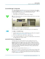
Страница 19: ...move the standard Ethernet cable from the management port 3 Connect the Landslide Manager to your LAN via a standard Ethernet connection from the management port to a router or switch Landslide Test Server Configuration All Ethernet ports are accessible from the front of the Landslide Test Server The management port is in the same location as on the Landslide Manager and is labeled Mgmt and logica...

Страница 20: ... management port configuration using IPv4 addressing Refer to page 24 for management port configuration using IPv6 addressing Note The procedures in this section use the following abbreviations TAS Landslide Manager Test Administration Server TS Landslide Test Server TAS TS A combination system comprised of both a Landslide Manager and Landslide Test Server running on the same server Follow the pr...

Страница 21: ...latform after all connections are made 4 Telnet to the management port from the laptop or workstation From a command prompt enter telnet 192 168 0 100 5 Use the cfguser account to telnet or login via console to a Landslide platform The default password is the same as the user name login cfguser password cfguser 6 The first time the cfguser user logs into Landslide the user should be prompted to de...

Страница 22: ...t TAS TS TAS TS IP Address Specify the IPv4 network mask then press Enter to continue port TAS TS TAS TS Network Mask Accept the default configuration to enable automatic speed and duplex negotiation by pressing Enter to continue port TAS TS TAS TS Auto Negotiate yes no yes Specify the address for the IPv4 gateway in your network then press Enter to continue port TAS TS TAS TS IP Gateway 10 The us...

Страница 23: ...e provisioning a Landslide Manager answer the resulting configuration prompts Specify a unique internal private IPv4 address that will not be used anywhere else within the Landslide management network An address such as 10 8 0 1 should work as this IP address is for use only within the private Landslide VPN network Press Enter to continue Enter the VPN server IP address 10 8 0 0 Specify the netmas...

Страница 24: ...ct Reboot now yes no yes Note If errors are detected in any of the data entered above answer no to the reboot question and rerun the ipcfg command To configure an IPv6 management port 1 Configure an Ethernet interface on a laptop or workstation with an IPv4 address and a network mask that will allow communications with the management port The default management port address is 192 168 0 100 Altern...

Страница 25: ...space key If errors are detected after data has already been entered at the end of the script answer no to the reboot question and rerun the ipcfg command 7 A warning will be displayed and the user will be asked if they wish to continue Type yes and press Enter to continue Note Do not terminate this utility otherwise it can lead to system instability Do you wish to Continue yes no no 8 The user wi...

Страница 26: ...fied to restore communication between the platforms 12 The VPN Service is currently only supported for an IPv4 management IP Address Press Enter to accept the default value of disable to skip configuration and continue Modify VPN Service status enable disable disable 13 A time server is defined for every platform Landslide supports both NTP and PTP Specify ntp or ptp and press Enter to proceed wit...

Страница 27: ...dress Configure TAS TS TAS TS alternate IPv4 Address mode none static dynamic none If static is selected answer the resulting configuration prompts Specify a unique IPv4 address for the alternate IPv4 management address then press Enter to continue port TAS TS TAS TS IPv4 Address Specify the IPv4 network mask then press Enter to continue port TAS TS TAS TS IPv4 Network Mask Specify the address for...

Страница 28: ...Initial Installation Management Port Configuration 28 Spirent Landslide Test System Installation Guide ...

Страница 29: ...uilt test system developed for testing and monitoring of live wireless packet data core network elements For a detailed description of system functionality refer to the online Help documentation In this chapter Landslide E10 Test System 30 Deployment 30 System Configuration Overview 32 Federal Communication Commission Interference Statement 33 ...

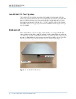
Страница 30: ...U X2 IuCS and WiFi SWu SWn features The EDGE software can support up to 50 UEs for LTE WiFi 3G technologies and up to two 2 eNodeBs Deployment The Landslide E10 test system is deployed in the field by connecting an RJ 45 cable between Ethernet ports made available at customer site and management port eth0 and one of the test ports eth1 or eth2 E10 includes three 3 ethernet ports Two 2 test ports a...

Страница 31: ...10 System Overview Deployment Spirent Landslide Test System Installation Guide 31 Figure 3 2 Landslide E10 Rear View Figure 3 3 Landslide E10 Side View Management Port Eth1 Test Port WiFi RF Antenna SMA Connectors ...

Страница 32: ...e E10 combined Manager and Test Server s 2 Provide an IP address on your management network for the Manager and for each Test Server Note The management network should be different from the test network that contains the devices systems under test 3 Configure the Manager s management port using the steps in Landslide Manager Configuration on page 19 4 Configure each Test Server using the steps in ...

Страница 33: ...experienced radio TV technician for help FCC Caution Any changes or modifications not expressly approved by the party responsible for compliance could void the user s authority to operate this equipment This device complies with Part 15 of the FCC Rules Operation is subject to the following two conditions 1 this device may not cause harmful interference and 2 this device must accept any interferen...

Страница 34: ...rning This equipment complies with FCC radiation exposure limits set forth for an uncontrolled environment The equipment must not be co located or operating in conjunction with any other antenna or transmitter For the 802 11AC version Contains Transmitter Module FCC ID TK4WLE900VX For the 802 11n version Contains Transmitter Module FCC ID RYK WPEA128N ...

Страница 35: ...r 4 Installing U1 OTA Modules on the Landslide E10 This chapter provides important information on mounting U1 Over the Air OTA module s to the E10 carrier and connecting to the E10 In this chapter Introduction 36 Before You Begin 36 Connecting the Antennas 42 ...

Страница 36: ...re USB connections Before You Begin Package Contents Check the contents of the package to ensure it is complete Each U1 LTE OTA module is shipped with 1 U1 OTA Module 2 LTE antennas 2 USB cables Instruction sheet Each E10 Carrier for U1 is shipped with 1 E10 Carrier for U1 Instruction sheet Important Refer to Federal Communication Commission Interference Statement for important information pertain...

Страница 37: ...full size SIM card into the slot until you hear a click and it latches the SIM card SIM cards are not included with the U1 OTA module and must be supplied by the user To remove the SIM card use a small flat screwdriver or fingernail to push it in until it clicks It will disengage the retention spring and release the SIM card Note The SIM card release is under spring tension use care when removing ...

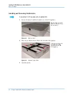
Страница 38: ...e Landslide E10 1 Remove the Spirent Landslide branded cover of the E10 Appliance Figure 4 2 Remove Cover 2 Place the new Module Carrier Plate on the Landslide E10 appliance Figure 4 3 Module Carrier Plate 3 Insert the module Use your finger or a small flat head screwdriver to pry the top cover off Orientate the plate so the spring tabs are facing toward the sides of the E10 Appliance ...

Страница 39: ...op plate can accommodate up to four U1 OTA modules Figure 4 5 Adding Additional Modules Set the module on the plate so that the USB port is facing away from the E10 Ensure that the antenna ports are also facing outward Slide the module along the guide rail until it stops The spring tab will click into the locked position All antenna ports and mini USB ports must be facing outward ...

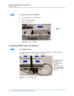
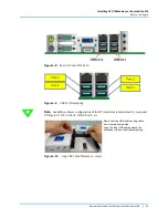
Страница 40: ...ule out Figure 4 6 Remove Module Connecting the USB Cables and Antennas To install USB cables The figures in this section show how to connect the modules to the USB ports on the Landslide E10 Figure 4 9 shows the port numbering Figure 4 7 Connect USB Cables Retaining spring Use long USB cables for modules furthermost from the E10 rear I O panel USB ports Use short USB cables for modules closest to...

Страница 41: ...f the E10 Figure 4 9 USB Port Numbering Note Landslide software configuration of the OTA modules is determined by rear panel USB port U1 OTA 1 Port1 OTA2 Port 2 etc Figure 4 10 Long USB Cable Placement step 1 Route the long USB cables using cable ties in between modules Loop the long USB cables above the antennas to prevent accidental pulling ...

Страница 42: ...Long USB Cable Placement step 2 Connecting the Antennas Connect the two antennas to each module 1 Insert each antenna into the SMA connectors on the side of the module 2 Grip the antenna nut rotate and tighten to secure the antennas to the module Drape the long USB cable over the antenna SMA connectors Secure the antennas to the module ...

Страница 43: ... a 90 degree position RF exposure warning This equipment complies with FCC radiation exposure limits set forth for an uncontrolled environment The equipment must not be co located or operating in conjunction with any other antenna or transmitter For the U1 LTE OTA Module Contains Transmitter Module FCC ID N7NMC7455 Pivot must be in the upright position Follow these steps to install the second ante...

Страница 44: ......

Страница 45: ...This chapter describes the System Administrator s initial login to the Landslide Performance Test System and the process for securing the system In this chapter Logging in to the System 46 Adding Test Servers to the System 47 Installing the Tcl API 47 Logging in to the System 46 ...

Страница 46: ... the Super User This is the account that will be used for the initial login In the Landslide Client window enter sms for the User Name and a1b2c3d4 for the Password and then click Login If the login is successful the main application window opens otherwise an error message explaining the reason for the login failure is displayed Note If this is your first login the Software End User License Agreem...

Страница 47: ...the Super User account and the cfguser account should be changed after installation in order to secure the system The Super User password can be changed while logged in as the Super User Follow the procedure in the Managing Your System Users Changing Your Password Help topic The cfguser account which was used to access the configuration tools during installation is also used to access the TAS Mana...

Страница 48: ...48 Spirent Landslide Test System Installation Guide ...

Страница 49: ...ports are located on the C100 Test Server the C50 combined Manager and Test Server or the C50 Add on Test Server The NIC configurations in this appendix have been selected to achieve the highest data throughput performance possible Other configurations are possible but can result in degraded throughput performance re ordering of port names or other unexpected behavior General 50 Supported NICs and...

Страница 50: ...ds Part Number Type Description Notes Configuration Tables L NIC 31A Quad port 1Gbps fiber Ethernet server adapter 1 GbE 10 100 1000Base SX C50 C50 S4 C100 C100 S2 C100 M2 C100 M4 All L NIC 32A Quad port 1Gbps copper Ethernet server adapter 1 GbE 10 100 1000Base T C50 C50 S4 C100 C100 S2 C100 M2 C100 M4 All L NIC 31B Quad port 1Gbps fiber Ethernet server adapter 1 GbE 10 100 1000Base SX C50 S4 C10...

Страница 51: ... A 7 through Table A 10 L ACC 006 Legacy IPSec Accelerator Card Legacy IPSec Accelerator Card C50 C100 C100 S2 C100 M2 Table A 11 and Table A 17 L ACC 007 Basic IPSec Accelerator Card Basic IPSec Accelerator Card C50 S4 C100 M4 Table A 2 through Table A 10 L ACC 008 High performance IPSec Accelerator Card High performance IPSec Accelerator Card C100 M4 only Table A 2 through Table A 10 L ACC 6002 ...

Страница 52: ...left of slot 1 Slots 0 and 6 are not used by Landslide In all other respects revision G and later chassis are identical to earlier revisions The standard factory default C100 M4 test server configuration includes two L NIC 32B quad port copper Ethernet NICs installed in slots 1 and 2 These NIC ports are labeled as eth2 through eth9 Optional add on test server appliances support the NIC configurati...

Страница 53: ... page 11 for contact details L ACC 008 can be used in lieu of L ACC 007 in C100 M4 configurations only Table A 2 One two three or four quad port 1 Gbps 4x 8x 12x or 16x 1 Gbps ports Slot Card Ports 0 Unused NA 1 First quad port 1 Gbps eth2 eth3 eth4 eth5 2 Second quad port 1 Gbps eth6 eth7 eth8 eth9 3 Fourth quad port 1 Gbps eth14 eth15 eth16 eth17 4 Third quad port 1 Gbps eth10 eth11 eth12 eth13 ...

Страница 54: ...rt 10 Gbps L NIC 66 eth10 eth11 eth12 eth13 5 Optional L ACC 007 or L ACC 008 IPSec Accelerator NA 6 Unused NA Table A 5 One quad port 10 Gbps NIC and one two or three quad port 1 Gbps NICs 4x 10 Gbps ports and 4x 8x or 12x 1 Gbps ports Slot Card Ports 0 Unused NA 1 First quad port 10 Gbps L NIC 66 eth2 eth3 eth4 eth5 2 First quad port 1 Gbps eth6 eth7 eth8 eth9 3 Third quad port 1 Gbps eth14 eth1...

Страница 55: ...ICs and one or two quad port 1 Gbps 8x 10 Gbps ports and 4x or 8x 1 Gbps ports Slot Card Ports 0 Unused NA 1 First quad port 10 Gbps L NIC 66 eth2 eth3 eth4 eth5 2 First quad port 1 Gbps eth6 eth7 eth8 eth9 3 Second quad port 1 Gbps eth14 eth15 eth16 eth17 4 Second quad port 10 Gbps L NIC 66 eth10 eth11 eth12 eth13 5 Optional L ACC 007 or L ACC 008 IPSec Accelerator NA 6 Unused NA ...

Страница 56: ...3 Empty NA 4 Second dual port 25 40 GbE NIC L NIC 73 74 eth4 eth5 5 Optional L ACC 007 or L ACC 008 IPSec Accelerator NA 6 Unused NA Table A 8 Three or four dual port 25 GbE or 40 GbE NICs with no additional NIC cards 6x or 8x 25 40 GbE ports Slot Card Ports 0 Unused NA 1 First quad port 10 Gbps L NIC 73 74 eth2 eth3 2 Second dual port 25 40 GbE NIC L NIC 73 74 eth4 eth5 3 Fourth dual port 25 40 G...

Страница 57: ...eth6 eth7 3 Third quad port 1 Gbps eth12 eth13 eth14 eth15 4 Second quad port 1 Gbps eth8 eth9 eth10 eth11 5 Optional L ACC 007 or L ACC 008 IPSec Accelerator NA 6 Unused NA Table A 10 Two dual port 25 GbE or 40 GbE NICs and one or two quad port 1 Gbps 4x 25 40 GbE ports and 4x or 8x 1 GbE ports Slot Card Ports 0 Unused NA 1 First dual port 25 40 GbE NIC L NIC 73 74 eth2 eth3 2 First quad port 1 G...

Страница 58: ...Ports 1 Second quad port 1 Gbps eth10 eth11 eth12 eth13 2 Quad port 10 Gbps L NIC 66 eth2 eth3 eth4 eth5 3 First quad port 1 Gbps eth6 eth7 eth8 eth9 4 Third quad port 1 Gbps eth14 eth15 eth16 eth17 5 Optional L ACC 006 IPSec Accelerator NA 6 Unused NA Table A 12 Two quad port 10 Gbps NICs and one or two quad port 1 Gbps NICs 8x 10 Gbps ports and 4x or 8x 1 Gbps ports Slot Card Ports 1 First quad ...

Страница 59: ...ports L ACC 006 IPSec Accelerator Card optional Slot Card Ports 1 Third quad port 1 Gbps eth10 eth11 eth12 eth13 2 First quad port 1 Gbps eth2 eth3 eth4 eth5 3 Second quad port 1 Gbps eth6 eth7 eth8 eth9 4 Fourth quad port 1 Gbps eth14 eth15 eth16 eth17 5 Optional L ACC 006 IPSec Accelerator NA Table A 14 One dual port 10 Gbps NIC and one two or three quad port 1 Gbps NICs 2x 10 Gbps ports and 4x ...

Страница 60: ... 10 Gbps NICs and one or two quad port 1 Gbps NICs 4x 10 Gbps ports and 4x or 8x 1 Gbps ports L ACC 006 IPSec Accelerator Card optional Slot Card Ports 1 First quad port 1 Gbps eth6 eth7 eth8 eth9 2 First dual port 10 Gbps AONIC eth2 eth3 3 Second dual port 10 Gbps AONIC eth4 eth5 4 Second quad port 1 Gbps eth10 eth11 eth12 eth13 5 Optional L ACC 006 IPSec Accelerator NA ...

Страница 61: ...ps NICs 2x 4x 6x or 8x 10 Gbps ports L ACC 006 IPSec Accelerator Card optional Slot Card Ports 1 Third dual port 10 Gbps AONIC eth6 eth7 2 First dual port 10 Gbps AONIC eth2 eth3 3 Second dual port 10 Gbps AONIC eth4 eth5 4 Fourth dual port 10 Gbps AONIC eth8 eth9 5 Optional L ACC 006 IPSec Accelerator NA Slot Card Ports 1 Third dual port 10 Gbps AONIC eth6 eth7 2 First dual port 10 Gbps AONIC eth...

Отзывы: