SPT-N11U and SPT-N12U Chassis Installation Instructions
Technical Specifications
SPT-N11U and SPT-N12U Installation Instructions
|
9
P/N 71-008728 Rev A, August 2019
•
Built-in Android
TM
touchscreen (SPT-N11U only)
•
SSH terminal emulation via Ethernet
•
Direct via external video connector and USB ports
•
Indicators and controls
•
System power on/off
•
Controller reset
•
Built-in LCD touchscreen (SPT-N11U)
•
Built-in LCD display (SPT-N12U)
•
Front panel LEDs:
–
Temperature, fan, admin link, system and system power status
–
Test module slot power status
•
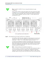
Rear panel LEDs:
–
Admin Ethernet link, speed and activity
–
Chassis synchronization Master/Slave and status
•
Connectors
•
Front panel: 4 x USB 2.0 (keyboard or mouse)
•
Rear panel:
–
DVI-I video (console)
–
2 x USB 2.0 (keyboard or mouse)
–
1 PPS and 10 MHz BNCs and DB9 serial DCE (for ETR support)
–
10/100/1000M BASE-T RJ-45 Ethernet (admin)
–
1588v2 Ethernet (supported on Rev. B controllers only)
–
Synch in/out RJ-45 (chassis synch chain)
–
System hard drive access panel


