SPT-N11U and SPT-N12U Chassis Installation Instructions
Powering the System
16
|
SPT-N11U and SPT-N12U Installation Instructions
P/N 71-008728 Rev A, August 2019
Note:
The SPT-N11U/SPT-N12U does not support redundant power supply
configurations.
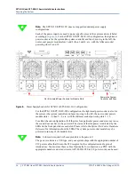
Each of the power inputs are used to power specific areas of the system and are labeled
accordingly (
). For the SPT-N11U/SPT-N12U-110 configuration, the rightmost
power socket is for the system (the system controller and fans); moving to the left, the
next socket powers module slots 1 and 2, then 3 and 4, etc., with the leftmost socket
powering slots 11 and 12.
Figure 8.
Power Supply Sockets for SPT-N11U/SPT-N12U-110 Configuration
For the SPT-N11U/SPT-N12U-220 configuration, the rightmost power socket is also for
the system (the system controller and fans); moving to the left, the next socket powers
module slots 1 - 4, then 5 - 8, etc., with the leftmost socket powering slots 9 - 12.
For either chassis configuration, if all the slots for a particular power socket are not in use,
the socket does not have to be powered. The status of the slot power is indicated by the
LEDs on the front panel above each slot. Please refer to the
Spirent TestCenter Hardware
Reference
for information about the LEDs. The system power socket must always be
powered to run any of the module slots.
Note:
2-slot cards require both occupied slots to be powered.
The power sockets are a C20 type, and your system ships with the appropriate number of
C19 power cables that fit into the C20 receptor for the configuration and region of
intended use. You must use these cables. Optionally, for connection to a PDU with the
appropriate number and sized circuits, ACC-2020A C20 to C19 power cords can be used.
Powers the System
Controller and Fans
Six (6) Labeled Power Sockets for Module Slots

