IM-P192-02
MI Issue 2
42
4.12 TVA communications
4.12.1 TVA UART set-up
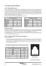
The TVA flowmeter has an EIA 232C compatible communications link and supports two
protocols: a simple Line Feed [LF] terminated ASCII protocol and a subset of Modbus/RTU.
This enables users to easily interrogate the TVA flowmeter for steam data using either a dumb
terminal or a P.C. loaded with a simple terminal emulation program or a standard Modbus
Master / Client application. The connection length is limited to 15 metres and must be in the
same building / area as the TVA flowmeter.
The TVA’s communication set up should be as follows:
TVA ASCII set-up
TVA Modbus set-up
Baud rate
1200 or 9600
Baud rate
1200 or 9600
Data bits
7
Data bits
8
Stop bits
one
Stop bits
one
Parity
none
Parity
none
Echo
off
Echo
off
Response time:
The TVA will start responding within 500 msec. The actual time to fully receive a response
from the TVA is baud rate dependent, for example a Modbus poll of 12 registers @1200 baud
rate could take ((5 + 24) bytes x ~10 ms / byte) + 500 ms ≈
800 ms
to complete.
The polling frequency can be faster if the polling algorithm is set to poll immediately after
receiving a valid response to a poll.
4.12.2 Using the EIA 232C communications
It is assumed that:
-
The electrical wiring for the EIA 232C communications has been carried out in accordance
with the EIA 232C standard. Please note the TVA EIA 232C connection requires a
connector RJ11 linked to a 9 way D-type adaptor. Figure 25 illustrates the TVA flowmeter's
RJ11 socket from the front.
The table below lists the RJ11 socket's pin connections.
The signals are named from the PC (or data terminal) end.
RJ11 pin
9-way D-type
Signal
1
Not used
2
4
DTR
3
5
GND
4
2
RX
5
3
TX
6
8
CTS
6 5 4 3 2 1
Pin numbers
Fig. 26 RJ11 socket


