IM-P192-02
MI Issue 2
44
4.14 Modbus communications
The TVA flowmeter has Modbus communications, in addition to the ASCII Modbus comms
that are available through the TVA RS232 port. An RS485 to RS232 converter is required, or
alternatively, an Ethernet to RS232 converter, both of which are widely available.
Modbus comms protocol
Format: Request frame
Address
1 byte
Function code
1 byte
Start address
2 bytes
Quantity of registers
2 bytes
Error check (CRC)
2 bytes
Total
8 bytes
Format: Response frame (normal)
Address
1 byte
Function code
1 byte
Byte count
1 byte
Register data
2 x Quantity of registers, MSB first, low register address first
Error check (CRC)
2 bytes
Total
5+ (2 x Quantity of registers) bytes
Format: Response frame (error)
Address
1 byte
Error code
1 byte (error code = function code plus 0x80)
Exception code
1 byte (01 or 02 see below)
Error check (CRC)
2 bytes
Total
5 bytes
Note:
Only ‘Read holding registers’ (function code ‘03’) is currently supported
4.14.1 ModBus request frame structure example.
Byte 1
Byte 2
Byte 3
Byte 4
Byte 5
Byte 6
Byte 7
Byte 8
Device
address
x
Function
code
(3)
Register
start
address
(MSB)
(0)
Register
start
address
(LSB)
(0)
Register
quantity
(MSB)
(0)
Register
quantity
(LSB)
(12)
CRC
(LSB)
x
CRC
(MSB)
x
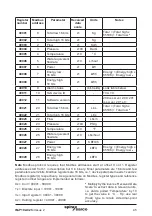
The above frame will poll all Modbus registers from Total low 16-bits up to and including
Software Version.


