


IM-P693-06
EMM Issue 1
21
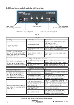
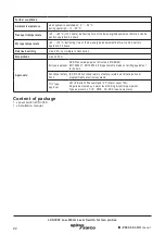
LCS3050 Low Water Level Switch for two probes
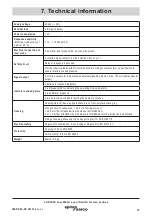
Supply voltage
24 Vdc +/– 20%
External fuse
0.5 A (semi-delay)
Power consumption
7 W
Response sensitivity
(Electrical conductivity of
water at 25 °C)
> 10 ... < 10000 μS/cm
Electrical connection of
level probe
2 inputs for level probe LP40, 4 poles, with screen.
Safety circuit
2 volt-free make contacts, 6 A 250 Vac/30 Vdc cos
j
= 1.
Delay of response: 3 seconds.
Provide inductive loads with RC combinations according to manufacturer's specification to
ensure interference suppression.
Signal output
2 volt-free outputs for instantaneous external signalling, 24 Vdc, max. 100 mA (semiconductor
output).
Indicators and adjustors
2 buttons for test and diagnosis,
2 red/green LEDs for indicating the operating mode and alarm.
3 red LEDs for diagnosis,
2 two-pole code switches for setting the number of probes.
Housing
Housing material: base: polycarbonate, black; front: polycarbonate, grey.
Cross section of connection: 1 x 4.0 mm
2
solid per wire or
1 x 2.5 mm
2
per stranded wire with sleeve to DIN 46228 or
2 x 1.4 mm
2
per stranded wire with sleeve to DIN 46228; terminal strips can be detached
Fixing of housing: Mounting clip on supporting rail TH 35, EN 60715
Electrical safety
Degree of contamination: 2, overvoltage category III to EN 61010-01.
Protection
Housing: IP 40 to EN 60529
Terminal strip: IP 20 to EN 60529
Weight
approx. 0.5 kg
7. Technical information