


IM-P693-06
EMM Issue 1
11
LCS3050 Low Water Level Switch for two probes
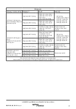
4.3 Explanatory notes to schematic representations
Fig. 5
Steam boiler plants according to EN 12952-07/ EN 12953-06, 72 h operation
Combination consisting of 2 level probes LP40 and 1 level switch LCS3050 as water level limiter.
Functional safety IEC 61508, SIL 3. The equipment combination meets the demand for two
independent water level limiters.
Fig. 6
(Pressurised) hot-water plants and electrically heated steam boilers according to EN 12953-06.
Steam boiler plants with high availability according to EN 12952-07 / EN 12953-06, 72h operation.
Combination consisting of 1 level probe LP40 and 1 level switch LCS3050 as water level limiter.
Functional safety IEC 61508, SIL 3. Hot water installations require two independent and separate
water level limiters. For this purpose one equipment combination LP40/LCS3050 shall be installed
in the hot-water boiler and the second one in the pressure maintaining vessel, the expansion tank
or the like (depending on the type of pressurisation). For electrically heated steam boilers one water
level limiter is sufficient. To meet the plant operator's demand for a higher level of availability of
the steam boiler plant, two (or three) independent equipment combinations LP40/LCS3050 can be
installed in the steam boiler.
Fig. 7
Combination consisting of 1 level probe LP40 and 1 level switch LCS3050 as water level limiter. The
level switch opens two separate safety circuits. Functional safety IEC 61508, SIL 3.
Further applications in accordance with national sets of regulations
Fig. 8
Combination consisting of 2 level probes LP40 and 1 level switch LCS3050 as water level limiter.
The level switch opens two separate safety circuits. Functional safety IEC 61508, SIL 3.
Further applications in accordance with national sets of regulations
Fig. 9
Combination consisting of 1 level probe LP40 and 1 level switch LCS3050 as water level limiter and 1
level probe LP40/1 level switch LCS3050 as first low-level alarm. Functional safety IEC 61508, SIL 3.
Further applications in accordance with national sets of regulations
Fig. 10
Combination consisting of 2 level probes LP40 and 2 level switches LCS3050 as water level limiter.
The level switch opens two separate safety circuits. Functional safety IEC 61508, SIL 3.
Further applications in accordance with national sets of regulations
Note
Please observe the safety-related characteristics for the equipment combination 1 level
probe LP40/level switch LCS3050 and 2 level probes LP40/level switch LCS3050 on
Table 1.
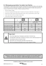
4.4 Supply voltage
Provide the level switch LCS3050 with an external semi-delay fuse 0.5 A.
Danger
For the supply of the level switch LCS3050 with 24 Vdc use a safety extra-low voltage
(SELV) power supply unit that must be electrically isolated from dangerous contact
voltages and must meet at least the requirements on double or reinforced isolation
acc. to EN 50178, EN 61010-1, EN 60730-1, EN 60950-1 or EN 62368-1 (safe isolation).