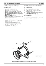
9 Repair
NGW 300 / LGW 300 / GBW 300
912
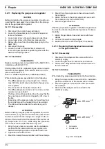
9.2.11 Replacing the gas pressure regulator
CAUTION
Before dismantling the gas press regulator, it must be en-
sured that the gas supply line is closed from the storage
tank to the gas pressure regulator.
9.2.11.1 Disassembly
1. Disconnect the coolant hoses with pliers.
2. Loosen the hose clamps on the coolant hoses and
remove the hoses.
3. Loosen and remove the gas intake and outlet lines.
4. Loosen and remove the reference pressure line.
5. Remove the hose from the safety valve (only for the
NGW 300).
6. Disconnect the plugs.
7. Loosen the nuts on the attachment screws and
remove the gas pressure regulator together with the
washers and spring ashers.
9.2.11.2 Installation
PLEASE NOTE
Replacement gas pressure regulators for the NGW 300 in
compliance with ECE-R 110:
Starting in March 2004, replacement gas pressure regula-
tors will only be supplied in the version which is in com-
pliance with ECE-R 110.
Order no. 9008612B (standard), 9009636A (IVECO)
When replacing, please pay attention to the following:
•
The differential pressure line (length: min. 100 mm,
max. 500 mm) is still only connected to the gas pres-
sure regulator.
•
The connection at the heater remains free.
•
The differential pressure line must run down, so that
no water can penetrate it.
•
The free end must be positioned in such a way that the
hose opening cannot become clogged by dirt, snow or
the like.
•
Influencing of the pressure ratios by the air flow from
the engine fan and the headwind must be avoided.
•
The line must be mounted in the vehicle (e.g with
clamps).
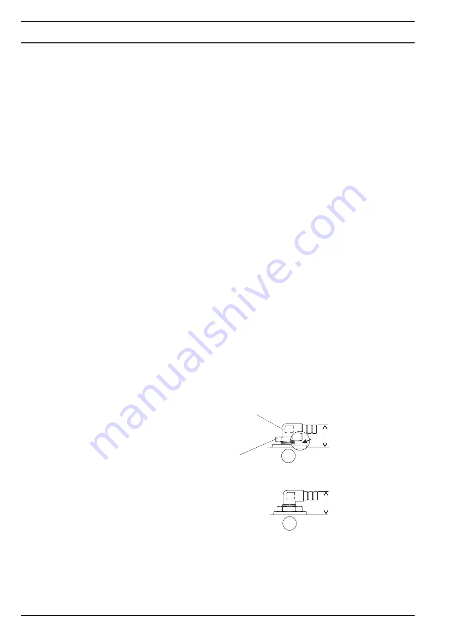
ATTENTION
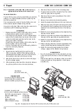
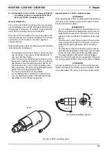
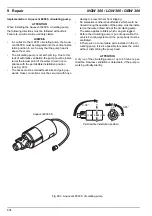
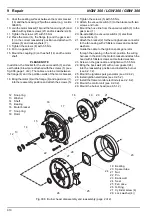
Before installing new gas pressure regulators, the enclo-
sed connector (1, fig. 910) for the reference pressure line
must be screwed into the casing cover, aligned in the di-
rection of the connection and secured with the counter nut
(2) (torque value 10 ± 1 Nm). While doing this‚ please ad-
here to the screw-in depth indicated in fig. 910.
1. Bring the gas pressure regulator into the installation
position with the attachment screws ,together with
washers and spring washers and attach with nuts.
2. Tighten the nuts with 5.5 Nm.
3. Mount the coolant hoses and attach with hose clamps.
4. Mount the reference pressure line and secure with
hose clamps.
5. Attach the hose to the safety valve and secure with
hose clamps (only for the NGW 300).
6. Mount the gas intake line.
ATTENTION
After the gas pressure regulator is installed, the gas intake
line must be checked by authorised personnel for imper-
meability.
7. Attach the gas intake hose and secure with hose
clamps.
8. Connect the electrical plugs again.
9. Examine the CO2 value and adjust, if necessary.
9.2.12 Replacing the delayed-action solenoid
in the gas intake line
9.2.12.1 Disassembly
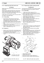
1. Disconnect the delayed-action solenoid from the
electricity supply.
2. Loosen the gas hose on both sides and remove.
3. Unscrew the delayed-action solenoid and remove it
from the bracket.
9.2.12.2 Installation
PLEASE NOTE
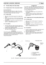
When installing, please pay attention to the flow direction..
1. Bring the delayed-action solenoid into the installation
position and attach it to the bracket with 2 screws.
2. Mount the gas hose on both sides and secure with
hose clamps.
3. Reconnect the delayed-action solenoid to the
electricity supply.
Fig. 910 Connector
min. 22 mm
min. 22 mm
+ 2
+ 2
1
2
2
1
1 Connector
2 Counter
nut

