NGW 300 / LGW 300 / GBW 300
9 Repair
909
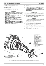
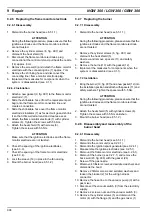
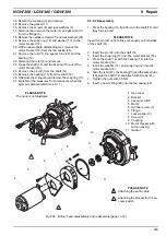
14. Detach the coupling (9) and remove.
15. Remove the gasket (11).
16. Remove the screws (8) and lock washers (7).
17. Dismount and remove the motor (4) and gas mixer (1)
from the flange (6).
18. Remove the cylinder screws (27) and lock washers (28).
19. Remove the snap ring (12) and washer (13) on the
motor bracket (16).
20. With an appropriate dismantling tool, remove the
motor bracket (16) from the fan casing (25).
21. Remove the nut (21), the spacer tube (20) and the
bearing (19).
22. Dismount the rotor (8) and remove.
23. Press the shaft (14) and the bearing (15) out of the
motor bracket (16).
24. Remove the pin (22) from the shaft (14).
25. Remove the bearing (15) from the shaft (14).
26. ORemove the O ring (26) and remove the snap ring (17).
27. Implement the measures for components, when the
system is disassembled (see 9.1.1).
9.2.8.2 Reassembly
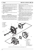
1. Press the bearing (15, fig. 908) onto the shaft (14) until
they form a bond.
PLEASE NOTE
Insert the pin (22) until it sticks out equally on both sides
of the shaft (14).
2. Insert the pin (22) into the shaft (14.
3. Insert the snap ring (17) into the motor bracket (16).
4. Press the shaft (14) with the bearing (15) into the
motor bracket (16).
5. Insert the washer (13) and snap ring (12) into the
motor bracket (16).
6. Slide the rotor (18), the bearing(19) and the spacer tube
(20) onto the shaft (14) and attach with screws (21).
7. Tighten the nuts with 5.5 Nm.
8. Insert a new O Ring (26) into the fan casing (25).
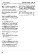
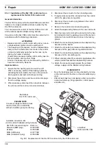
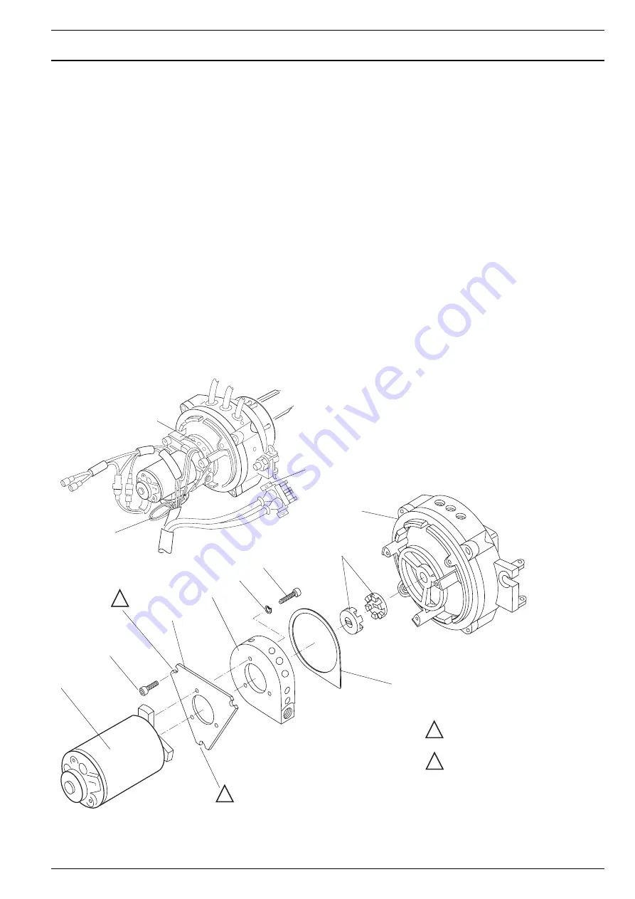
Fig. 908 Burner head disassembly and reassembly (page 1 of 2)
2
1 Gas mixer
2 Bracket
3 Vacuum switch
4 Motor
5 Cylinder screw (3)
6 Flange
7 Lock washer (3)
8 Screw (3)
9 Coupling
10 Motor bracket with
mit fan casing
11 Gasket
PLEASE NOTE
Attaching the earth cable
Attaching the bracket for the va-
cuum switch
1
1
2
1
7
8
9
10
4
5
6
11
2
1
3
PLEASE NOTE
The hood is not illustrated.

