11
(a)
(b)
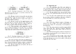
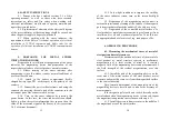
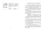
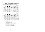
Fig.3.4. Displaying information on the IN-01m stress
indicator screen when the power is turned on (a) and after the
measurement mode is set (b)
3.4.3. Button 6 is used to turn on the stress indicator
screen backlight. When you turn on button 6, the screen is
illuminated with additional light to improve the display of
digital stress indicator readouts.
3.4.4. Button 7 is used to save measurements to the
electronic memory of the stress indicator. When the button 7 is
turned on or off, the current transmitter reading displayed on
the screen is recorded in the stress indicator memory.
3.4.5. When connecting a cable connected to the USB
port of a personal computer to the mini-USB 11 connector,
information about establishing a connection with the personal
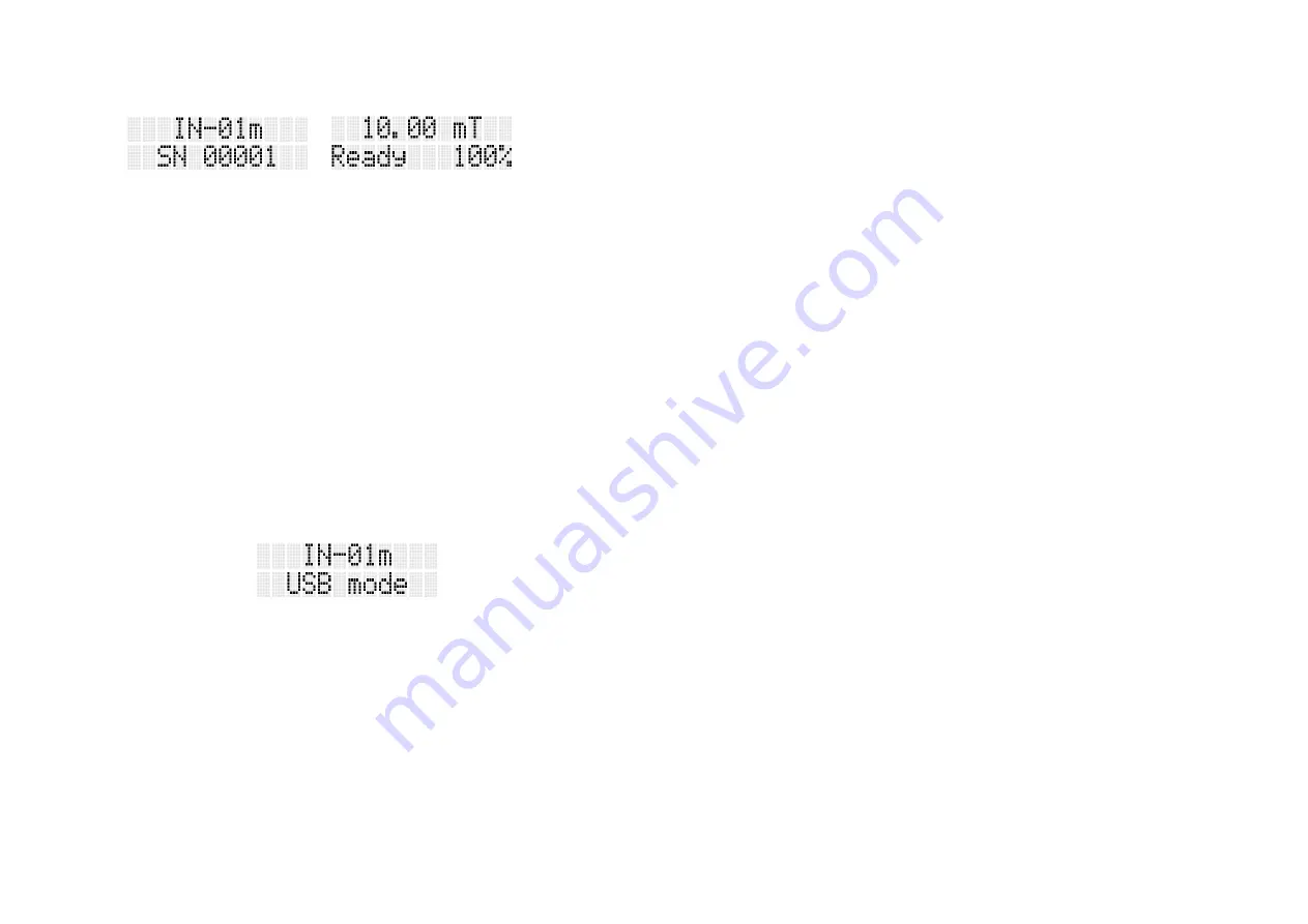
computer appears on the stress indicator screen (Fig. 3.5).
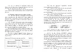
Fig.3.5. Displaying information on the IN-01m stress
indicator screen when connected to a personal computer
Using of the IN-01m Connect software application pre-
installed on a personal computer, the measured information
from the stress indicator's electronic memory is transmitted
over a cable and stored in the personal computer's memory.
3.4.6. Button 8 displays the current date and time of
stress indicator on the screen.
12
3.5. Magnetizing unit
3.5.1. The magnetizing unit of the stress indicator is
used for magnetizing the local metal section of a steel product
or metal structure with a constant magnetic field, the intensity
vector of which is directed perpendicular to the metal surface.
3.5.2. The magnetizing device is non-volatile, single-
pole, rod type. It uses permanent magnets made from rare earth
metals.
3.5.3. The pole of the magnetizing device is protected
by an overlay to ensure convenience in the process, the handle
of the magnetizing device is provided with a strap.
3.6. Sensor
3.6.1. The stress indicator sensor is designed to
measure the field strength of the residual magnetization of
metal over the surface of a local section of a steel product or
metal structure.
3.6.2. The sensor contains a precision integrated Hall
Effect sensor chip and a precision integrated temperature
sensor chip with an analog signal output, which are located in
a single housing.
3.6.3. The Hall sensor plane is located in the center of
the transducer housing parallel to the working surface at a
distance of 0.5 mm from it.
3.6.4. To measure the field strength of the residual
magnetization of the metal, the center of the working surface
of the stress indicator
sensor
is set in the middle of the residual
magnetized area of the metal.


