


15
6.1.3. To measure the field strength of the residual
magnetization on the surface (in mT) and to assess the value of
the mechanical stress of the metal based on the dependence of
the field strength of the residual magnetization on the
magnitude of mechanical stress of the metal (see the
Appendix), appropriate to the grade of steel.
If the calibration constants programmed into the
memory of the stress indicator in manufacture, the display on
the stress indicator screen will correspond to the value of the
mechanical stress of the metal for this steel grade (in MPa).
6.1.4. To measure the mechanical stress of the metal on
another section of the steel product, the metal structure should
repeat the operation according to steps 6.1.1-6.1.3.
6.2. Measuring the tension of steel studs and bolts
Measuring the tension of steel studs and bolts of
threaded connections consists in pre-magnetizing their end
surface with a constant magnetic field of the magnetizing
device and measuring the field strength of the residual
magnetization of the metal above it.
6.2.1. Install the magnetizing device on the end surface
of the steel stud or bolt and smoothly remove it from the
magnetized surface in a perpendicular direction.
Note: lateral displacement of the magnetic pole of the
magnetizing device is not allowed to reduce the accuracy of
measurements.
If the magnetic pole is allowed to shift laterally on the
metal surface when the magnetizing device is removed, repeat
the magnetization operation according to step 6.2.1.
6.2.2. Install the stress indicator sensor in the middle
area of the magnetized end surface of the steel stud or bolt.
6.2.3. To measure the field strength of the residual
magnetization on the surface (in mT) and to assess the value of
the mechanical stress of the metal (torque) on the basis of
dependence of the field strength of the residual magnetization
16
on the magnitude of mechanical stress of the metal (see the
Appendix) for the corresponding grades of steel studs, bolts.
6.2.4. When checking a large number of steel studs,
bolts located on a separate unit of the body product, the
operations according to steps 6.2.1-6.2.3 should be performed
for each steel stud, bolt.
Note: uniformity of the tightening force of all steel
studs, bolts is achieved when the stress indicator readouts on
all controlled studs, bolts have approximately the same value
within the measurement error.
6.3. Charging or replacing the battery
6.3.1. As the resource of the PP3 type battery is used
up, the stress indicator screen in the zone indicating the battery
charge level (see Fig.3.4 b) set the current charging level in %.
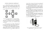
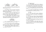
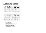
6.3.2. When the battery charge level decreases relative
to the allowed threshold value, the stress indicator screen will
display a flashing message
Recharge battery!
(Fig.6.1).
Fig.6.1. Message on IN-01m the stress indicator about
the need to charge or replace the battery
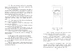
When you reach that level you need to charge the
battery, which in the electronic connector block to connect the
power adapter cable of the charger and connect it to the
network voltage of 220V, 50 Hz.
Fig.6.2. Indication of the battery charge process on the
IN-01m stress indicator screen


