


Deflector Settings
9.1.2 Amplifier Check
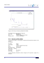
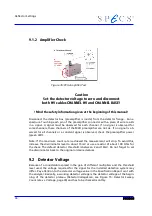
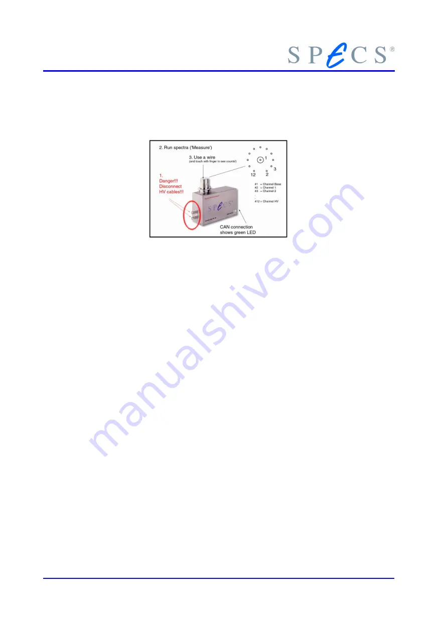
Figure 35: PCU Amplifier Test
Caution
Set the detector voltage to zero and disconnect
both HV cables CHANNEL HV and CHANNEL BASE!
! Mind the safety information given at the beginning of this manual!
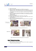
Disconnect the detector box (preamplifier is inside) from the detector flange. Run a
spectrum. Touching each pin of the preamplifier connector with a piece of wire results
in a signal. A signal must be observed for each channel. If no signal is observed for
some channels, these channels of the MCD preamplifier are not ok. If no signal is ob-
served for all channels or a constant signal is observed, check the preamplifier power
(green LED).
Note: If the maximum count rate is achieved the measurement will stop. To avoid this,
increase the discriminator level to about 15mV or use a resistor of about 100 Ohm for
the check. The default detector threshold is between 2 and 10mV. Do not forget to set
the discriminator back to the original or desired values.
9.2 Detector Voltage
Because of a considerable spread in the gain of different multipliers and the threshold
level used, the voltage required for the signal for the installed detection system may
differ. Pay attention to the detector voltage value in the Specification Report sent with
the analyzer. Basically, a working detector voltage is the detector voltage at the begin-
ning of the detector plateau (DetectorVoltageScan, see Figure 15: Detector Sweep,
Count rate vs. Voltage, page 30) and has to be checked monthly.
76
Содержание PHOIBOS 100
Страница 1: ...PHOIBOS Hemispherical Energy Analyzer Series PHOIBOS 100 PHOIBOS 150 3 1...
Страница 6: ...Table of Contents PHOIBOS...
Страница 10: ...Introduction 4 PHOIBOS...
Страница 13: ...Electrical Connections Figure 2 Connection Scheme PHOIBOS 7...
Страница 14: ...Components and Connections Figure 3 Analyzer Housing PHOIBOS100 8 PHOIBOS...
Страница 15: ...Electrical Connections Figure 4 Analyzer Housing PHOIBOS150 PHOIBOS 9...
Страница 42: ......
Страница 51: ...SpecsLab Hardware and Software Installation PHOIBOS 45...
Страница 52: ......
Страница 62: ......
Страница 78: ...Analyzer Checks Figure 33 Schematics of the 12 pin Analyzer Feedthrough 72 PHOIBOS...
Страница 80: ......
Страница 86: ......
Страница 92: ...List of Figures Figure 39 Alignment Pin 84 II PHOIBOS...
Страница 93: ...List of Figures PHOIBOS III...
Страница 94: ......
Страница 96: ......
Страница 98: ...Index PHOIBOS...


