


Unit Operation
5.3 Detailed Operation
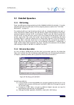
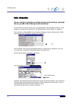
5.3.1 Slit Setting
There are different settings available with the PHOIBOS Slit Orbit mechanism. To under-
stand the possible slit combination for this analyzer please see section 3.4, “Slit Orbit
Mechanism” on page 22.
The optimum setting is reached when entrance slits are aligned along the lens axis, i.e.
when the particle number passing through the lens stages and impinging on the hemi-
spherical capacitor entrance slit S1 is a maximum. There is also the correct position for
the exit slit S2. Usually there are only two exit slits, therefore physical stops in both dir-
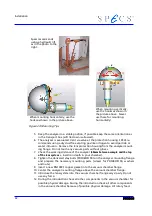
ections means that this is also the correct exit slit position. In positioning the feed-
through (Figure 12: External Rotary Dial for Positioning page 24) to the slit locations,
the rotary dial is internally fixed near to the right value by a physical rest position.
Please check the marking at the rotary for the desired combination. Additionally, a
check
via the viewport for alignment may help. A typical slit combination for standard
XPS and large samples (10x10mm) is 2:7x20mm / 2:open.
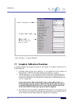
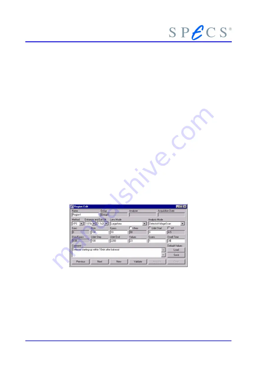
5.3.2 Detector Operation
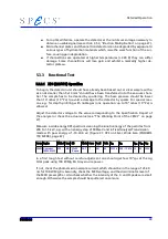
For new multiplier (CEM) please read the start-up procedure given for the CEM after
bake out in section 4.6 . The normal procedure after bake out is increasing the detector
voltages in small steps (100V) over a period of 10 min without excitation.
Figure 25: Starting up the detector
Operating conditions:
●
A dry-pumped or well-trapped/diffusion-pumped operating environment is de-
sirable. A poor vacuum environment can shorten CEM life or change the operat-
ing characteristics.
●
A pressure of 1
⋅
10
-5
mbar or lower is preferred. Higher pressure can result in
high background noise due to ion feedback.
●
Voltage should be applied to the MCD in small (100 - 200 V) steps.
48
Содержание PHOIBOS 100
Страница 1: ...PHOIBOS Hemispherical Energy Analyzer Series PHOIBOS 100 PHOIBOS 150 3 1...
Страница 6: ...Table of Contents PHOIBOS...
Страница 10: ...Introduction 4 PHOIBOS...
Страница 13: ...Electrical Connections Figure 2 Connection Scheme PHOIBOS 7...
Страница 14: ...Components and Connections Figure 3 Analyzer Housing PHOIBOS100 8 PHOIBOS...
Страница 15: ...Electrical Connections Figure 4 Analyzer Housing PHOIBOS150 PHOIBOS 9...
Страница 42: ......
Страница 51: ...SpecsLab Hardware and Software Installation PHOIBOS 45...
Страница 52: ......
Страница 62: ......
Страница 78: ...Analyzer Checks Figure 33 Schematics of the 12 pin Analyzer Feedthrough 72 PHOIBOS...
Страница 80: ......
Страница 86: ......
Страница 92: ...List of Figures Figure 39 Alignment Pin 84 II PHOIBOS...
Страница 93: ...List of Figures PHOIBOS III...
Страница 94: ......
Страница 96: ......
Страница 98: ...Index PHOIBOS...


