background image

7

AIR FOR COMBUSTION 

AND VENTILATION

Continued

DETERMINING FRESH-AIR FLOW 
FOR HEATER LOCATION

Determining if You Have a Confined or 
Unconfined Space

Use this work sheet to determine if you have a 

confined or unconfined space.

Space:

  Includes  the  room  in  which  you  will 

install heater plus any adjoining rooms with door-

less  passageways  or  ventilation  grills  between 

the rooms.

1.  Determine the volume of the space (length x 

width x height).
Length x Width x Height =__________cu. ft. 

(volume of space)

Example: 

Space  size  22  ft.  (length)  x  18  ft. 

(width) x 8 ft. (ceiling height) = 3168 cu. ft. 

(volume of space)
If  additional  ventilation  to  adjoining  room  is 

supplied with grills or openings, add the volume 

of these rooms to the total volume of the space. 

2.  Multiply the space volume by 20 to determine 

the maximum Btu/Hr the space can support.
 __________ (volume of space) x 20 = (Maxi-

mum Btu/Hr the space can support)

Example:

 3168 cu. ft. (volume of space) x 20 = 

63,360 (maximum Btu/Hr the space can support)

3.  Add the Btu/Hr of all fuel burning appliances in 

the space.


Vent-free fireplace 

 ___________ Btu/Hr

Gas water heater* 

 ___________ Btu/Hr

Gas furnace 

 ___________ Btu/Hr

Vented gas heater 

 ___________ Btu/Hr

Gas fireplace logs 

 ___________ Btu/Hr

Other gas appliances*  + __________ Btu/Hr
Total 

= __________ Btu/Hr

* Do not include direct-vent gas appliances. Di-

rect-vent draws combustion air from the outdoors 

and vents to the outdoors.

Example:

Gas water heater 

__________ Btu/Hr

Vent-free fireplace 

+  ________ Btu/Hr

Total 

=  ________ Btu/Hr

4.  Compare the maximum Btu/Hr the space can 

support with the actual amount of Btu/Hr used.


 _________Btu/Hr (maximum the space can support)


 _________Btu/Hr (actual amount of Btu/Hr used)


Example:

  63,360 Btu/Hr (maximum the space 

can support) 


79,000  Btu/Hr  (actual  amount  of 

Btu/Hr used)

The space in the above example is a confined space 

because the actual Btu/Hr used is more than the maxi-

mum Btu/Hr the space can support. You must provide 

additional fresh air. Your options are as follows:
A.  Rework worksheet, adding the space of an adjoin-

ing room. If the extra space provides an unconfined 

space, remove door to adjoining room or add 

ventilation grills between rooms. See 

Ventilation 

C.  Install a lower Btu/Hr fireplace, if lower Btu/Hr 

size makes room unconfined. 

If the actual Btu/Hr used is less than the maxi-

mum Btu/Hr the space can support,


the space is 

an unconfined space. You will need no additional 

fresh air ventilation.

 WARNING: If  the area in which 

the  heater  may  be  operated  is 

smaller  than  that  defined  as 

an  unconfined  space  or  if  the 

building  is  of  unusually  tight 

construction, provide adequate 

combustion and ventilation air 

by one of the methods described 

in the 

National Fuel Gas Code, 

ANSI Z223.1/NFPA 54 Section 5.3


or applicable local codes.

  40,000
  39,000
  79,000

Air From Inside Building, 

pag

e 8

.

B.  Vent room directly to 

tion Air From Outdoors, 

page .

the outdoors. See 

Ventila-

 8

Содержание 57N

Страница 1: ...ion This appliance may be installed in an aftermarket permanently located manu factured mobile home where not prohib ited by local codes This appliance is only for use with the type of gas indicated on the rating plate This appliance is not convertible for use with other gases WARNING Improper installation adjust ment alteration service or maintenance can cause injury or property damage Refer to t...

Страница 2: ...ance be kept clean Safety Information 3 Local Codes Specifications 4 Locating Firebox 5 Product Specifications 5 Air For Combustion and Ventilation 6 Installation 8 Framing 10 Operating Fireplace 19 This unit was tested and listed to ANSI Z21 11 2 2011 by OMNI Test Laboratories Inspecting Burners 23 Cleaning and Maintenance 24 Troubleshooting 25 Proflame Wiring Diagram 29 llustrated Parts Breakdow...

Страница 3: ... be present even though no odor exists Make certain you read and understand all warnings Keep this manual for reference It is your guide to safe and proper operation of this heater WARNING Any change to this heater or its controls can be dangerous WARNING Do not use a blower insert heat exchanger insertorotheraccessorynotap proved for use with this heater WARNING Do not allow fans toblowdirectlyin...

Страница 4: ...ther objects SAFETY INFORMATION Continued 11 Do not use fireplace if any part has been exposed to or under water Immediately call a qualified service technician to inspect the fireplace and to replace any part of the control system and any gas control which has been under water 12 Turn fireplace off and let cool before servicing Only a qualified service person should service and repair fireplace 13 Ope...

Страница 5: ...d Pressure 10 0 W C Inlet Gas Pressure in of water ModeP Orifice size 1 75 mm Shipping Weight 135 lbs Orifice size 34 Shipping Weight 135 lbs Btu Variable 24 000 34 000 Btu Variable 23 000 34 000 Type Gas Natural Gas Ignition Electronic Manifold Pressure 3 5 W C Inlet Gas Pressure in of water Maximum 10 5 Minimum 5 0 Maximum 13 0 Minimum 11 0 2 Everything needed to complete installation 3 Proper a...

Страница 6: ...ings of unusually tight construction you must provide additional fresh air Unusually tight construction is defined as construction where a walls and ceilings exposed to the out side atmosphere have a continuous water vapor retarder with a rating of one perm 6 x 10 11 kg per pa sec m2 or less with openings gasketed or sealed and b weather stripping has been added on openable windows and doors and c ...

Страница 7: ...t vent draws combustion air from the outdoors and vents to the outdoors Example Gas water heater __________ Btu Hr Vent free fireplace ________ Btu Hr Total ________ Btu Hr 4 Compare the maximum Btu Hr the space can support with the actual amount of Btu Hr used _________Btu Hr maximum the space can support _________Btu Hr actual amount of Btu Hr used Example 63 360 Btu Hr maximum the space can supp...

Страница 8: ... IMPORTANT Do not provide openings for inlet or outlet air into attic if attic has a thermostat controlled power vent Heated air entering the attic will activate the power vent Figure 2 Ventilation Air from Outdoors Figure 1 Ventilation Air from Inside Building Outlet Air Ventilated Attic Outlet Air Inlet Air Inlet Air Ventilated Crawl Space To Crawl Space To Attic INSTALLATION NOTICE This heater ...

Страница 9: ...ntilation page 6 IMPORTANT Make sure the fireplace is level If fireplace is not level it will not work properly CHECK GAS TYPE Use the correct gas type natural or propane LP for your fireplace If your gas supply is not cor rect do not install fireplace Call dealer where you bought fireplace for proper type fireplace WARNING This appliance is equipped for natural or pro pane LP gas Field conversion is no...

Страница 10: ...ION Neverconnectpro pane LP fireplace directly to the propane LPsupply Thisfireplace requires an external regulator notsupplied Installtheexternal regulator between the fireplace and propane LP supply INSIDE CHASE INSTALLATION 18 5 RECESSED INSTALLATION 18 5 0 50 0 50 VENT FREE FIRE RIBBON FRAMING DIMENSIONS FASTENING TABS IN USE COMBUSTIBLE MATERIAL NON COMBUSTIBLE MATERIAL AREA FACING DIMENSIONS MI...

Страница 11: ...GRANITE MARBLE STONE OF NON COMBUSTIBLE MATERIAL OPTION 1 NON COMBUSTIBLE MATERIAL min 49 NON COMBUSTIBLE MATERIAL minimum 49 wide X 30 high FACING WITH ONE LAYER THREE WAYS TO ALLOW AIR FLOW TO FRONT AIR VENT LEAVE MINIMUM 1 2 X 26 SLOT CLEAR FOR THE LOUVER AREA min 30 18 36 5 ...

Страница 12: ...ST LAYER TOP VIEW ALLOW AIRFLOW SIDE VIEW ALLOW AIRFLOW OF NON COMBUSTIBLE MARBLE STONE OPTION 2 NON COMBUSTIBLE MATERIAL NON COMBUSTIBLE MATERIAL IE DUROCK CEMENT BOARD GRANITE min 49 min 49 ALLOW FOR MINIMUM 13 SQUARE INCHES OF AIR FLOW ALLOW FOR MINIMUM 13 SQUARE INCHES OF AIR FLOW min 30 minimum 49 wide X 30 high min 30 MATERIALS FACING WITH TWO LAYERS 18 36 5 18 36 5 ...

Страница 13: ...BEHIND SURROUND INTO AIR VENT SIDE VIEW NON COMBUSTIBLE ALLOW MINIMUM 13 SQUARE INCHES OF AIR FLOW NOTCH OUT BACK OF FACE MATERIAL TO ALLOW MINIMUM 13 SQUARE INCHES OF AIR FLOW ALLOWING AIR FLOW FROM BEHIND SURROUND FACING WITH THICK LAYER OF NON COMBUSTIBLE MATERIAL VIEW FROM BACK OF SURROUND ...

Страница 14: ...dition and Canadian Electrical Code CSA C22 1 INSTALLATION Continued This fireplace requires 110V AC electrical supply for normal operation in order to power up supplied 7V AC DC adapter which is required to operate Remote Control However during power outage situation its electronic system DFC board can be temporary powered with 9V DC batery and main valve can be operated manually using ON OFF pos...

Страница 15: ... equipment shutoff valve union and plugged 1 8 NPT tap Locate NPT tap within reach for test gauge hook up NPT tap must be upstream from fireplace IMPORTANT Install equipment shutoff valve in an accessible location The equipment shutoff valve is for turning on or shutting off the gas to the appliance Check your building codes for any special re quirements for locating equipment shutoff valve to fire...

Страница 16: ...from equipment shutoff valve to fireplace Route flexible gas supply line through one of the access holes 3 Attach the flexible gas line to gas supply as per Figure 7 Check tightness of flexible gas line attached to gas regulator of fireplace and check all gas connections for leaks see Checking Gas Connections page 16 CHECKING GAS PRESSURE 1 Check gas type The gas supply must be the same as stated ...

Страница 17: ...ng main gas valve located on or near gas meter for natural gas or using compressed air 3 Check all joints from gas meter to equipment shutoff valve for natural gas or propane LP supply to equipment shutoff valve for propane LP Apply noncorrosive leak detection fluid to all joints Bubbles forming shows a leak 4 Correct all leaks at once PRESSURE TESTING FIREPLACE GAS CONNECTIONS 1 Open equipment sh...

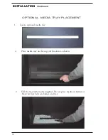
Страница 18: ...TION 1 Locate optional media tray 2 Place media tray on the support brackets as shown 3 Fill the tray with media supplied Do not place media on burner or block air flow between burner and tray OPTIONAL MEDIA TRAY PLACEMENT ...

Страница 19: ...0 80 C 2 D D 7 8 5 3 6 If 0 4 33 REMOTE 5 2 o OPERATING INSTRUCTIONS 6 to 7 7 8 0 If 0 45 1 9 1 1 30 7 r n to Wiring Diagram on page 29 8 4 1 33AB 31 access panel i e inner cover or optional media 2 Make sure that fresh set of are installed If necessary c 1 ...

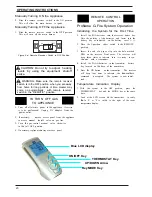
Страница 20: ...TIONS If i 0 0 If 1 If r media tray or a 0 2 3 4 2 3 0 13 n 456 5 1 47 3 8 1 5 5 9 546 6 5 d Fig 1 Proflame Transmitter Blue LCD display ON OFF Key THERMOSTAT Key UP DOWN Arrow KeyMODE Key Manually Manually now 3 8 0 that ...

Страница 21: ...21 OPERATING INSTRUCTIONS T 0 0 1 1 1 3 4 1 3 h ard F D turn o will If y 1 key F 3 ...

Страница 22: ... Commanded Fireplace State Opened IPI OFF REMOTE and OFF received Turn OFF Flames OFF Opened IPI ON REMOTE and ON received Turn ON Pilot Main burner flames ON Closed CPI OFF REMOTE and OFF received Pilot ON Pilot flame ON Closed CPI ON REMOTE and ON received Turn ON Pilot Main burner flames ON 4 OPERATING INSTRUCTIONS P ...

Страница 23: ... in Figure 19 Correct Burner Flame Pattern Note The correct pilot flame on natural gas units will have a slight curve but flame should be blue and have no yellow or orange color Figure 17 shows a correct pilot flame pattern Figure 18 shows an incorrect Figure 20 If burner flamepatternis incorrect as shown in Figure 20 Incorrect burner flame pattern caused by port blockage see Troubleshooting page 25 ...

Страница 24: ...lot flame indicates dust and dirt in the pilot as sembly There is a small pilot air inlet hole about two inches from where the pilot flame comes out of the pilot assembly see Figure 22 With the unit off lightly blow air through the air inlet hole You may blow through a drinking straw if compressed air is not available The primary air inlet holes allow the proper amount of air to mix with the gas T...

Страница 25: ...use a wire needle or similar object to clean ODS pilot This can damage ODS pilot unit Note All troubleshooting items are listed in order of operation 1 n 2 turned Turn o 24 OBSERVED PROBLEM POSSIBLE CAUSE REMEDY 7 Low batteries 7 Replace batteries in remote control and receiver re program the receiver 2 2 0 3 Defective DFC module 3 Replace DFC module ...

Страница 26: ...AUSE REMEDY 0 1 2 2 1 3 4 3 1 1 1 out fl f t 1 7 3 3 1 r 4 4 4 1 ram 9 1 5 supplier 7 Defective DFC module 7 Replace DFC module 24 page 24 or replace burner orifice 2 Clean burner or replace burner orifice page 24 5 Defective DFC module 5 Replace DFC module ...

Страница 27: ...27 OBSERVED PROBLEM POSSIBLE CAUSE REMEDY TROUBLESHOOTING Continued 2 3 1 3 a 24 If f 24 V 0 remote 12 3 on 2 3 3 6 6 1 0 7 4 7 7 8 9 9 22 ies are 3 re program receiver 5 24 Key Lock ...

Страница 28: ...ghbor s phone Follow the gas supplier s instructions If you cannot reach your gas supplier call the fire department IMPORTANT Operating fireplace where impurities in air exist may create odors Cleaning supplies paint paint remover cigarette smoke cements and glues new carpet or textiles etc create fumes These fumes may mix with combustion air and create odors These odors will disappear over time 0 0...

Страница 29: ...INPUT 7 Volt DC STABILIZED SUPPLY OUTPUT MOTOR RECEIVER DC SUPPLY SPLIT FLOW ON OFF TPTH TH DFC SUPPLY DC SUPPLY GROUND 885 PROFLAME Orange Green 11 29 17 18 4 20 19 16 21 This diagram shows replaceable SIT Proflame parts used in your fireplace please refer to pages 31 ...

Страница 30: ...ILLUSTRATED PARTS BREAKDOWN 1 2 3 4 5 6 7 8 9 10 30 19 17 20 21 4 1 22 11 13 for references see page 31 ...

Страница 31: ...CTOR 1 11 F200066 F200066 SUPPLIED SHUTOFF VALVE 1 12 W800008 W800008 MEDIA TRAY OPTIONAL not shown 1 13 W800007 W800007 INNER COVER 1 14 H200014 H200014 SPARK WIRE V F PILOT 1 15 C100020 C100020 DUPLEX POWER OUTLET not shown 1 16 H200001 H200001 PROFLAME GTM TRANSMITTER 1 17 H200010 H200010 PROFLAME GTM RECEIVER 1 18 H100140 H100140 7V AC DC POWER ADAPTER 1 19 H100142 H100142 SIT DFC CONTROL BOAR...

Страница 32: ...orkmanship Spark BASIC WARRANTY Modern Fires will at its option replace or repair the defective components at no charge to the original owner Spark Modern Fires will also pay for reaonable labor costincurred in replacing or repairing such components for a period of two years from date of installation Any products presented for warranty repair must be accompanied by a dated proof of purchase and ma...

Отзывы: