background image

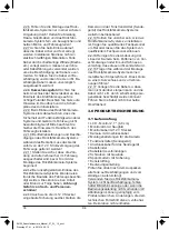
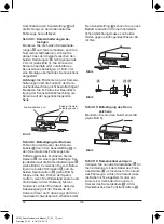
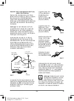
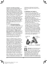
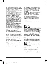
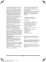
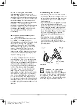
Step 2: Hole for camera cable

Now look for an opening / drill hole near 
the license plate opening into the interior 
of the vehicle to feed the connector cable 
plug of the camera      into the interior of 
the vehicle. For added visibility and easy 
installation remove the interior trim near 
the license plate. If the vehicle has no 
opening, drill a hole using an 11 mm 
(diameter) drill bit in the area covered by 
the license plate. 

Caution:

 be sure there are no 

electrical wires or other auto-
motive parts in the area where 

you will be drilling which could be 
damaged! 
 
To protect the borehole in the metal panel 
from corrosion the metal edges should be 
coated with a suitable paint coating (e.g. 
automaker‘s touch-up pen) and allow to 
dry adequately.
 

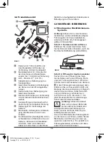
1

2

3
4

5

6

7

9

10

11

1

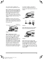
Image 2

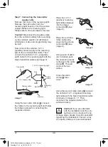
Step 1: Remove license plate

First remove the rear license plate and, if 
applicable, also the license plate frame 
(see image 2).

Caution!

 Due to differences in technical 

and design-related vehicle types, these 
instructions for use do not apply to all 
vehicle models.

4.1 Installing the backup camera     

      system

4.0 INSTALLATION / 

      OPERATION

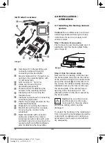
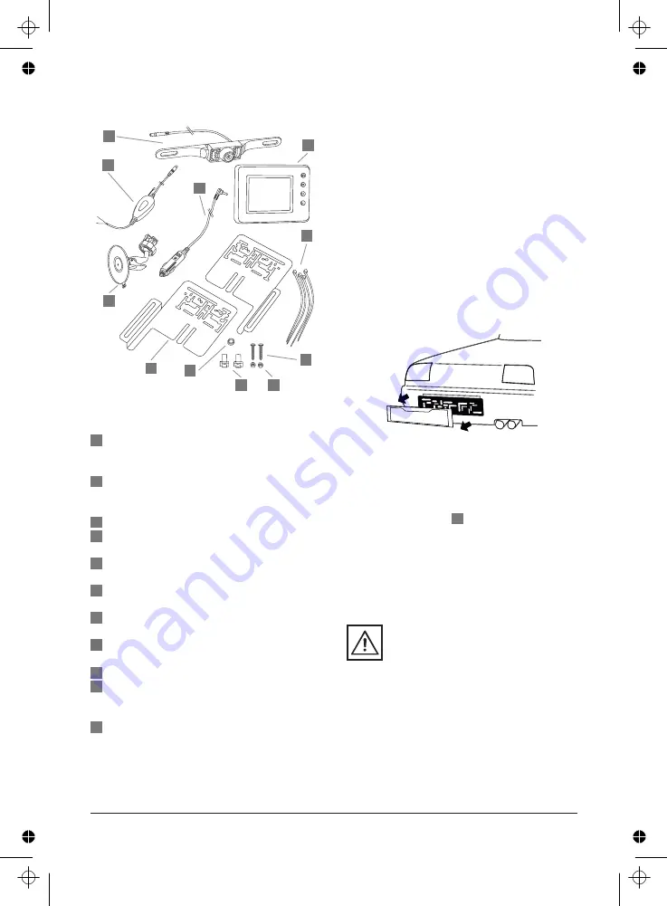
Camera with 7 infrared LEDs and 
connection cable with plug for 
connecting to the transmitter 
Monitor cable with 12 V plug for con-
necting to the cigarette lighter, with 
1A (ampere) fuse
LCD monitor 2,7 " (6,8 cm)
Cable ties for securing the 
transmitting equipment
Thread screws for attaching the 
camera to the mounting bracket
Clamping nuts for securing the 
thread screws
Clamped connections for connecting 
to reversing light wires
Plastic ring as edge protector for the 
cable feed boreholes
Brackets for mounting the camera
Monitor arm with suction cup base 
for securing the monitor to the 
windshield
Radio transmitter with connector 
cable and socket to the camera, 
including connector cable with a red 
and black cable for connecting to the 
reversing light und affixed adhesive 
strip for attaching the transmitter.

3.2 Product overview

8

GB

20

10

3

4

2

1

5

6

7

8

9

11

Image 1

98106_Rueckfahrkamera_Manual _27_03_12_print

Dienstag, 27. M

rz 2012 14:09:15

Содержание Ecoline 98106

Страница 1: ...Notice d utilisation 28 CZ N vod na pou itie 41 SK N vod k pou it 54 R CKFAHRKAMERA Rear camera system Syst me de cam ra de recul Syst m couvac kamery C vac kamerov syst m 98106 98106_Rueckfahrkamera...

Страница 2: ...wechseln 4 7 Fehlersuche R ckfahrkamera Systems 4 0 MONTAGE BEDIENUNG 3 1 Lieferumfang 3 2 Produkt bersicht 3 0 PRODUKTBESCHREIBUNG 2 1 Allgemeine Sicherheitshinweise 2 2 Sicherheitshinweise zur Monta...

Страница 3: ...legtem R ckw rts gang die Aufnahme der Kamera mit einem Funksignal vom Transmitter Sender an den Monitor gesendet Der Blickwinkel der Kamera betr gt 110 Durch die einge baute Nachtsichttechnik ist ein...

Страница 4: ...Kinderh nde gelangen und bewahren Sie es f r Kinder unzug nglich auf Die Klein teile k nnten von Kindern verschluckt wer den und Kinder k nnten daran ersticken Kinder k nnten sich bei der Verwendung d...

Страница 5: ...Gegenst nde m glicherweise berstrahlt und nicht klar angezeigt 2 1 23 Nach der Reinigung eines Fahr zeugs in einer Autowaschanlage ist es m glich dass aufgrund mechanischer Einwirkungen der Erfassung...

Страница 6: ...ss die Kabel sicher und fest verlegt werden Installieren Sie diese nicht an elektrisch leitf higen Materialien Falls Kabel durch scharfkantige W nde Bleche etc verlegt werden m ssen Leerrohre oder Kab...

Страница 7: ...zeuginnere gelangen kann Entfernen Sie zur besseren Einsicht und Montage die Innenverkleidung im Bereich des Nummernschildes Sollte keine ff nung am Fahrzeug vorhanden sein bohren Sie ein Loch mit ein...

Страница 8: ...nmuttern siehe Bild 5 Stoppen Sie das Drehen der Spann muttern wenn Sie Widerstand sp ren und die Kamera mit der Halterung fest ver bunden ist Achten Sie darauf dass der Kabelausgang auf der R ckseite...

Страница 9: ...Legen Sie das 12 V Plus Kabel der R ckfahrleuchte seitlich in den Klemmverbinder ein siehe Bild 8 Bild 8 Bild 9 Bild 10 Bild 11 Legen Sie das rote Kabel des Trans mitters seitlich in den Klemmverbind...

Страница 10: ...damit der Umgebungsbereich der Kamera verdun kelt wird und der Nachtsichtsensor aktiv wird Lassen Sie eine kleine ffnung zwischen Ihren Daumen und sehen Sie in die Handfl chen hinein Ist die Kamera a...

Страница 11: ...instellen Bild auf den Kopf und links rechts Einstellung Richtlinien Zu oder abschaltbar Sprache Spracheinstellung Englisch Deutsch Exit Men modus beenden Dr cken Sie im Modus Exit eine oder Taste um...

Страница 12: ...auf dem Monitor ist aber nichts zu sehen Es besteht keine Verbin dung zwischen Kamera und Monitor M glicherweise sind die Kabel der Kamera nicht korrekt angeschlos sen bzw haben sich gel st Pr fen Sie...

Страница 13: ...240 Pixel Abmessung ca 100 x 75 x 22 mm L x B x H mm Technik LCD Farbdisplay Stromversorgung 12 V Volt Gleichstrom Sicherung 1 A Ampere Sicherungstyp T1AL250V Kamera Aufl sung 640 x 480 Pixel Nachtsi...

Страница 14: ...Kaufdatum Grund f r die Reklamation Fehlerbe schreibung 8 0 GARANTIE UND SERVICE 7 1 2 Zur Entsorgung der Verpackungs materialien sind die geltenden Gesetze zur M llbeseitigung zu beachten 7 1 1 Eine...

Страница 15: ...g the backup camera system 4 6 Replacing fuses 4 7 Troubleshooting 4 0 INSTALLATION OPERATION 3 1 Contents 3 2 Product overview 3 0 PRODUCT DESCRIPTION 2 1 General safety instructions 2 2 Safety instr...

Страница 16: ...amera picture is wirelessly transmitted from the sender to the monitor The camera angle of view is 110 The built in night vision technology also allows image transmission in the dark When shifting out...

Страница 17: ...dren do not understand or recognize the potential risks associated with handling electrical equipment Keep the backup camera system out of the reach of children and store out of the reach of children...

Страница 18: ...r the backup camera system or this system near other wireless equipment 2 1 19 Be sure all plugs and power cables are dry Never power on the equipment with moist or wet hands 2 1 18 The camera is prot...

Страница 19: ...pecialist 2 2 13 Even if the fuse inside the 12 V plug is tripped backup camera system s camera and wireless transmitter will remain ready for use 2 2 12 Improper installation of the backup camera sys...

Страница 20: ...technical and design related vehicle types these instructions for use do not apply to all vehicle models 4 1 Installing the backup camera system 4 0 INSTALLATION OPERATION Camera with 7 infrared LEDs...

Страница 21: ...a is securely connected to the bracket Be sure the cable outlet at the back of the camera always points upward to maintain the maximum swivel range Step 3 Mounting the camera brackets Mount the two ca...

Страница 22: ...t the cables to the reversing light and follow the following steps for connecting the respective cables 7 7 7 7 7 7 Image 11 Image 10 Image 9 Image 8 Transmitter Earth Black 12 V supply cable Image 7...

Страница 23: ...l loads in the direct vicinity of the transmitter to avoid impairing the transmission Now secure the camera and transmitter cables run in the void of the trunk with cable ties The cables run may not i...

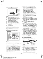
Страница 24: ...tton to access menu mode The display will now show the menu settings for approx 7 seconds The respective adjustment mode will be displayed in yellow font Each time the button M is pressed again the me...

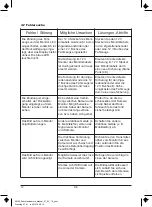
Страница 25: ...ection between the camera and the monitor The camera cables may not be correctly connected or have loosened Check if the camera connection cable is correctly and securely connected to the reversing li...

Страница 26: ...0 TECHNICAL SPECIFICATIONS 5 1 5 If the camera joint loosens over time you may readjust it There are 4 screws at the back of the camera inside the camera bracket Slightly tighten these screws to secur...

Страница 27: ...Reason for the claim description of defect 8 0 WARRANTY AND SERVICE 7 1 2 Follow the applicable waste management laws when disposing of packaging 7 1 1 Any disposal and recycling of the backup camera...

Страница 28: ...cam ra de recul 4 6 Changer le fusible 4 7 Recherche d erreurs 4 0 MONTAGE UTILISATION 3 1 Contenu de l emballage 3 2 D tail du produit 3 0 DESCRIPTION DU PRODUIT 2 1 Consignes g n rales de s curit 2...

Страница 29: ...envoy e par un signal radio de l metteur l cran L angle de vision de la cam ra est de 110 Gr ce la technologie int gr e de vision nocturne une transmission de l image par l metteur est galement possi...

Страница 30: ...s 2 1 3 Cet appareil ne doit pas tre utilis par des personnes enfants y compris aux capacit s physiques sensorielles ou mentales limit es ou manquant d exp rience et ou de connaissances moins qu elles...

Страница 31: ...is l appareil avec des mains mouill es ou humides 2 1 18 La cam ra est prot g e contre la pluie mais n est pas tanche Ne la plongez pas dans l eau ni dans aucun autre liquide 2 1 17 Il faut viter que...

Страница 32: ...M me si le fusible int gr la prise 12 V se d clenche la cam ra et l metteur radio du syst me restent fonctionnels 2 2 12 En cas de montage incorrect du syst me les composants lectroniques du v hicule...

Страница 33: ...voir image 2 Attention En raison des diff rents types de v hicules la technologie et la structure vari es la pr sente notice de montage n est pas valable pour tous les v hicules 4 1 Montage du syst me...

Страница 34: ...serrer les crous lorsque vous sentez une r sistance et que la cam ra est fix e sur le support Veillez ce que la sortie du c ble soit toujours tourn e vers le haut sur le c t arri re de la cam ra pour...

Страница 35: ...de c ble Rouge 12 V DC Feux de recul tape 7 Connecter le c ble d alimen tation avec l metteur Retirez le cache des feux de recul Retirez le support de l ampoule du carter Recher chez les c bles du v h...

Страница 36: ...enclench e contr ler l alimentation de la cam ra avec un test simple Ne d marrez pas le moteur Recouvrez la cam ra avec les deux paumes de main pour foncer l environnement de la cam ra et activer le c...

Страница 37: ...rche arr t pour que le symbole de la touche s allume en bleu Pour activer le menu appuyez sur la touche M Les param tres de menu apparaissent l cran pendant env 7 secondes Chaque param tre est affich...

Страница 38: ...tre que les c bles de la cam ra ne sont pas correctement branch s ou qu ils se sont d branch s Contr lez que les c bles d alimentation de la cam ra sont bien connect s aux c bles des feux de recul et...

Страница 39: ...5 Si l articulation de la cam ra se desserre au fil du temps vous pouvez la resserrer Sur l arri re de la cam ra se trouvent 4 vis l int rieur du support Serrez les l g rement pour obtenir une meille...

Страница 40: ...lus de la copie du ticket de caisse avec date de l achat de la raison de la r clamation descrip tion du dysfonctionnement 8 0 GARANTIE ET SERVICE APR S VENTE 7 1 2 Pour l limination de l emballage res...

Страница 41: ...uvac ho kamerov ho syst mu 4 6 V m na pojistky 4 7 Vyhled v n chyb 4 0 MONT OBSLUHA 3 1 Obsah dod vky 3 2 P ehled v robku 3 0 POPIS V ROBKU 2 1 V eobecn bezpe nostn pokyny 2 2 Bezpe nostn pokyny pro m...

Страница 42: ...r a p i za azen zp te n rychlosti na n j kamera vys l obraz p en en r diov m sign lem Kamera m zorn hel 110 Vestav n technika no n ho vid n umo uje p enos obrazu i za tmy Po za azen jin ho rychlostn h...

Страница 43: ...te p stupu d t k couvac mu kamerov mu syst mu D ti nevn maj nebo nerozeznaj mo n nebezpe p i zach zen s elektrick mi p stroji Nedovolte aby couvac kamerov syst m dostal do d tsk ch rukou uchov vejte...

Страница 44: ...hem provozu syst mu m e doj t k poruch m bezdr tov ch p stroj nap mobiln ch telefon p stroj s Bluetooth anebo mohou tyto vyvolat poruchy kamery Proto nepou vejte takov p stroje v bl zkosti syst mu neb...

Страница 45: ...n ka nebo si nechte instalo vat syst m na zak zku 2 2 13 I p i spr vn aktivaci pojistky v z str ce pro nap t 12 V z st v kamera a vys la couvac ho kamerov ho syst mu i nad le provozuschopn 2 2 12 Neod...

Страница 46: ...D ky r zn m technik m a konstru kc vozidel neplat a nen tento n vod k mont i syst mupou iteln do v ech typ vozidel 4 1 Mont couvac ho kamerov h syst mu 4 0 MONT OBSLUHA Kamera se 7 infra erven mi LED...

Страница 47: ...ba rouby a matky viz obr zek 5 Zastavte utahov n matek uc t te li odpor a je li kamera pevn spojena s dr ky Dbejte na to aby byl kabel kamery pro zachov n maxim ln mo n ho v kyvu kamery vyveden na zad...

Страница 48: ...tlo pou ijte ob kabelov svorky a postu pujte podle n sleduj c ch popsan ch krok pro p ipojen jednotliv ch kabel Vys la Uzemn n ern Nap jec kabel pro 12 V Obr zek 7 Kabel kamery Kamera Couvac sv tlo Ka...

Страница 49: ...nitor tla tkem P i spr vn m p ipojen vys la e obdr od n j monitor sign l p i za azen zp te n ho p evodov ho stupn a na monitoru se objev obraz prostoru za vozidlem Jestli e se na monitoru obraz neobje...

Страница 50: ...nitoru Kontrast nastaven kontrastu monitoru Barva Nastaven intenzity barev na monitoru Sm r nastaven zobrazen na monitoru Obraz na hlav a nastaven vlevo vpravo Linie zapnut nebo vypnut Jazyk nastaven...

Страница 51: ...mus se vym nit Zapalov n je zapnut zp te ka za azen na monitoru nen nic vid t Neexistuje spojen mezi kamerou a monitorem Pravd podobn nejsou spr vn zapojen kabely kamery nebo se uvolnily Zkontrolujte...

Страница 52: ...5 1 5 Jestli e se kloub kamery asem uvoln m ete ho se dit Na zadn stran kamery se nach zej 4 rouby uvnit dr ku kamery Pro lep dr en v kyvn kamery m ete tyto rouby pon kud p it hnout K tomu je nutn de...

Страница 53: ...n likvidaci materi lu do odpadu plat z kony pro likvidaci odpadu 7 1 1 Likvidace do odpadu a recyklace couvac ho kamerov ho syst mu mus b t provedeny podle z konn ch ustanoven Informujte se u Va obce...

Страница 54: ...aciehoho kamer syst mu 4 6 V mena poistky 4 7 Vyh ad vanie chyby 4 0 MONT OVL DANIE 3 1 Obsah dod vky 3 2 Preh ad produktu 3 0 POPIS V ROBKU 2 1 V eobecn bezpe nostn pokyny 2 2 Bezpe nostn pokyny pre...

Страница 55: ...a pri zaradenom sp tnom chode vysiela kamera sn mok pomocou sign lu od transmitra vysiela a na monitor Uhol poh adu kamery in 110 V aka zabudovanej technike no n ho videnia je mo n prenos obrazu vysi...

Страница 56: ...d det Deti nech pu alebo nerozoznaj mo n nebezpe enstv spo vaj ce v styku s elektric pr strojmi Nedovo te aby sa c vac kam syst m dostal do r k de om a skladujte ho na mieste nedostupnom pre deti Mohl...

Страница 57: ...e norm lne alebo monitor nezobrazuje objekty jasne 2 1 20 C vac kam syst m m e po as prev dzky ru i in bezdr tov pr stroje napr mobiln tel bluetooth pr stroje alebo by t mito ru en Nepou vajte preto t...

Страница 58: ...m person lom 2 2 13 I ke sa poistka zabudovan v 12 V z str ke aktivuje ostan kamera a transmiter vysiela c vacieho kamero v ho syst mu na alej prev dzkyschopn 2 2 12 Pri neodbornej mont i c vacieho k...

Страница 59: ...r znorod ch typov vozidiel nie je tento in tala n n vod platn a pou ite n pre v etky typy vozidel 4 1 Mont c vacieho kamerov ho syst mu 4 0 MONT OVL DANIE Kamera so 7 infra erven mi LED a pripojovac...

Страница 60: ...up nacie matice Pozri obr 5 Presta te to i up nacie matice ke poc tite odpor a kamera je pevne spojen s up nan m Dbajte na to aby ukon enie k bla na zadnej strane kamery v dy ukazovalo nahor aby bol z...

Страница 61: ...ou ite obe k blov spojky a dodr te nasleduj ce kroky pre spojenie pr slu n ch k blov Transmiter vysiela Uzemnenie ern 12 V z sobo vac k bel Obr zok 7 Kamerov k bel Kamera Sp tn svetlomet K blov spojka...

Страница 62: ...a stupe II ne tartujte motor Zapnite monitor tla tkom Ak je transmiter spr vne zapojen je pri zaraden spiato ky vyslan sign l na monitor a rozsah vidite nosti a zobraz na monitore Ak sa na monitore ne...

Страница 63: ...e jasnosti monitora Kontrast nastavenie kontrastu monitora Farba nastavenie intenzity farieb Smer nastavenie zobrazenia monitora Obraz obr tene a z ava zprava nastavenie Smerov iary zapn alebo vypn Ja...

Страница 64: ...e nie je ni vidie Ch ba spojenie medzi kamerou a monitorom K ble kamery s pravde podobne nespr vne zapojen pr p sa uvo nili Skontrolujte i s pripo jovacie kamery spr vne a pevne zapojen na k ble sp tn...

Страница 65: ...syst m pri extr mnych teplotn ch v kyvoch Vtedy vznikaj ca konden zovan voda m e po kodi elektroniku 5 1 2 C vac kamerov syst m istite suchou handri kou Nepou vajte iadne tekutiny alebo siln istiace p...

Страница 66: ...i likvid cii obalov ch materi lov dodr iavajte platn z kony pre likvid ciu odpadu 7 1 1 Likvid cia a op tovn pou itie c vacieho kamerov ho syst mu mus zodpoveda pr vnym ustanoveniam Informujte sa o to...

Страница 67: ...mPartnerAutoteile GmbH Co Industriestr 31 CH 8112 Otelfingen SPA Systems s r o Pod Vi ovkou 1661 37 140 00 Praha 4 Kr esk republika www spa automotive com Original Bedienungsanleitung 19 03 2012 98106...

Отзывы: