background image

South Bend Tools

For Machines Mfd  Since 1/21

Model SB1493

-19-

O P E R A T I O N

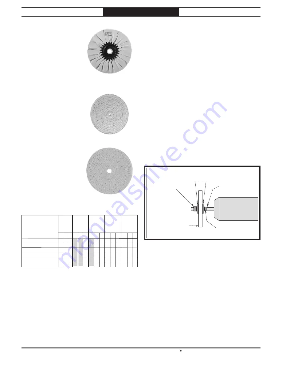
Airway Soft

Made of 100% cotton 

sheets and held 

together with a steel 

retainer  Pleats in the 

material help hold 

compound  These 

wheels are great for 

polishing soft metals 

and   plastics 

Laminated Sisal

Designed for rough 

cutting, sisal works 

well with various steels, 

copper, aluminum, 

and brass to remove 

scratches and prepare 

the piece for polishing 

Spiral Sewn

Consist of layers of 

100% unbleached cotton 

sheeting that are spiral 

sewn 

1

8

" apart  Works 

well for initial polish on 

brass, stainless steel, 

aluminum, bronze and 

cast iron 

Buffing Sequence:  R = Rough   F= Final Cut, Initial Polish   P = Final Polish

Plastics 

Soft 

Metals

Thin 

Plating 

Gold 

Silver

Chrome  

Nickel 

Plate

Copper 

Brass 

Aluminum

Iron

Steel

Stainless 

Steel

Buff Style
Loose Muslin-Soft
Loose Muslin-Hard
Airway Hard
Airway Soft
Laminated Sisal
Spiral Sewn

R   F   P R   F   P R   F   P R   F   P

R   F   P

X

X

X

X

X

X

X

X

X

X

X

X

X

X

X

X

X

X

X

Buffing Wheel Sequence Key

X

X

Installing/Removing 
Buffing Wheel

The spindle shafts protruding from either side 

of the motor make it easy to swap out different 

buffing wheels for different projects  Install an 

appropriate wheel for your operation with a 

5

/

8

bore 

Tools Needed 

Qty

Open-End Wrenches 

7

/

16

"                                       2

To install/remove buffing wheel:

1.

  DISCONNECT MACHINE FROM POWER!

2.

  Remove spindle hex nut and outer flange 

from each end of spindle (see Figure 13


Note: Left spindle shaft has left-hand 

threads so hex nut threads counterclockwise 

onto sleeve.

5

/

8

" Hex Nut

Wheel

Flanges

16mm Bushing

19mm Bushing

Figure 13. Buffing wheel order of installation.

3.

  Remove old buffing wheels (if installed)  DO 

NOT remove inner flange or bushings 

4.

  Install desired buffing wheels between inner 

and outer wheel flanges (see Figure 13)  

5.

  Secure wheels and flanges with spindle hex 

nuts removed in Step 2 

Содержание SB1493

Страница 1: ...A Tradition of Excellence South Bend Tools January 2021 by South Bend Tools For Machines Mfd Since 1 21 MODEL SB1493 1 HP VARIABLE SPEED BUFFER OWNER S MANUAL...

Страница 2: ...on is a process that happens through training and experience If you are not an experienced operator of this type of machinery read through this entire manual then learn more from an experienced operat...

Страница 3: ...ng 11 Location 12 Bench Mounting 13 Assembly 13 Power Connection 14 Test Run 14 OPERATION 16 Operation Overview 16 Disabling Switch 17 Buffing 17 Selecting Buffing Wheels 18 Installing Removing Buffin...

Страница 4: ...entire manual and received proper training Spindle Secures and spins buffing wheels Accepts 5 8 bore wheels of up to 12 diameter Wheel Flanges Hold buffing wheel Bushings Support flange to hold buffi...

Страница 5: ...Horsepower 1 1 2 HP Phase Single Phase Amps 7A 3 5A Speed 900 3600 RPM Type TEFC Induction Power Transfer Direct Bearings Shielded Permanently Lubricated Model SB1493 Page 1 of 2 Model SB1493 1 1 2 HP...

Страница 6: ...el Speed Rating 3600 RPM Spindle Spindle Speed 900 3600 RPM Spindle Diameter 5 8 in Spindle Thread Pitch 11 TPI Spindle Length Usable 5 15 16 in Right Spindle Thread Direction Right Handed Left Spindl...

Страница 7: ...as follows Death or catastrophic harm WILL occur Moderate injury or fire MAY occur Death or catastrophic harm COULD occur Machine or property damage may occur Basic Machine Safety Owner s Manual All...

Страница 8: ...by verifying that all fastening devices are properly secured and items attached to spindles have enough clearance to safely rotate Chuck Keys or Adjusting Tools Tools used to adjust spindles chucks o...

Страница 9: ...nots large splinters sharp edges and DO NOT buff knives cable chain or other potentially dangerous objects that may be grabbed by the buffing wheel and thrown at the operator Eye Face Lung Protection...

Страница 10: ...e covered in detail later in this section The typical preparation process is as follows 1 Unpack the machine and inventory the contents of the box crate 2 Clean the machine and its components 3 Identi...

Страница 11: ...hat meets the requirements in the following section Full Load Current Rating Full Load Rating at 110V 7 Amps For your own safety and protection of property consult an electrician if you are unsure abo...

Страница 12: ...replace it with a new one Extension Cords Minimum Gauge Size 14 AWG Maximum Length Shorter is Better 50 ft We do not recommend using an extension cord with this machine If you must use one only use i...

Страница 13: ...ient and do a careful job when cleaning and removing the rust preventative The time you spend doing this will reward you with smooth sliding parts and a better appreciation for the proper care of the...

Страница 14: ...described in this manual Physical Environment The physical environment where your machine is operated is important for safe operation and longevity of parts For best results operate this machine in a...

Страница 15: ...h Lag Screw Flat Washer Figure 6 Direct Mount setup Assembly The machine must be fully assembled before it can be operated Before beginning the assembly process refer to Required for Setup on Page 8 a...

Страница 16: ...discover a problem with the operation of the machine or its safety components do not operate it further until you have resolved the problem Note Refer to Troubleshooting on Page 23 for solutions to c...

Страница 17: ...run machine 1 Clear away all tools and objects used during preparation and assembly 2 Turn variable speed dial all the way counterclockwise and make sure ON OFF switch is in OFF position see Figure 8...

Страница 18: ...e is used during operation so they can more easily understand the controls discussed later in this manual Note Due to the generic nature of this overview it is not intended to be an instructional guid...

Страница 19: ...d the workpiece how much pressure to apply how to move the workpiece against the wheel and how much compound to use requires a certain amount of trial and error Thoroughly clean all parts you plan to...

Страница 20: ...her apron Also wear a dust mask to protect your lungs from microscopic particulate that will be flying off wheel Use caution when polishing plated metals there is a chance that thinly plated materials...

Страница 21: ...Loose Muslin Hard Airway Hard Airway Soft Laminated Sisal Spiral Sewn R F P R F P R F P R F P R F P X X X X X X X X X X X X X X X X X X X Buffing Wheel Sequence Key X X Installing Removing Buffing Wh...

Страница 22: ...ipoli provides an excellent medium cut for brass aluminum and zinc alloy Green Fine Slightly more abrasive than the extra fine green this green compound is great for a medium to fine polish with most...

Страница 23: ...d Rouge Low cost must have Due to their nature colors may vary Figure 16 Model G2582 Buffing Compound Set Installing unapproved accessories may cause machine to malfunction resulting in serious person...

Страница 24: ...ly Inspect for worn damaged cord Inspect for worn ON OFF switch or variable speed dial Monthly Clean vacuum dust buildup off motor Always disconnect machine from power before performing maintenance or...

Страница 25: ...ceeds recommended wheel rating 2 Replace with smaller wheel or reduce wheel width 3 Motor overheated 3 Clean motor let cool and reduce workload 4 Circuit board at fault 4 Test replace circuit board 5...

Страница 26: ...ble results including serious injury or fire Motor Wiring The motor wiring shown in these diagrams is current at the time of printing but it may not match your machine Always use the wiring diagram in...

Страница 27: ...Panel Circuit Board BASE Main Circuit Board CROWN AGE05010F12L DC12V 0 15A Fuse BUSSMAN 10A 250V 680uF 250V S Cap 12V 15W 0 47uF K 310V CX1603 680uF 250V S Cap JT3 JT2 JT1 JW JV JU GND TX TX RX RX VDD...

Страница 28: ...26 For Machines Mfd Since 1 21 South Bend Tools Model SB1493 E L E C T R I C A L Electrical Component Pictures Figure 20 Control unit wiring Figure 22 Start capacitors Figure 21 Switch wiring...

Страница 29: ...04 STRAIN RELIEF TYPE 1 1 2 16 PSB1493016 T BUSHING 19 X 32 X 9 5 PSB1493005 FLANGE SCREW 10 24 X 1 4 17 PSB1493017 WHEEL FLANGE 5 8 6 PSB1493006 CONTROL PANEL UNIT 18 PSB1493018 HEX NUT 5 8 11 7 PSB1...

Страница 30: ...eeves and DO NOT wear loose clothing gloves or jewelry 6 Always hold workpiece firmly with both hands throughout the buffing operation 7 Disconnect power before changing wheels adjusting or servicing...

Страница 31: ...standard of any domestic or foreign government industry or authority In no event shall South Bend s liability under this warranty exceed the original purchase price paid for this machine Any legal act...

Страница 32: ...southbendtools com Printed In Taiwan CS21588...

Отзывы: