background image

Grounding Requirements

This machine must be grounded! In the event 

of certain types of malfunctions or breakdowns, 

grounding provides a path of least resistance 

for electric current in order to reduce the risk of 

electric shock.

Improper connection of the equipment-grounding 

wire can result in a risk of electric shock. The 

wire with green insulation (with or without 

yellow stripes) is the equipment-grounding wire. 

If repair or replacement of the power cord or 

plug is necessary, do not connect the equipment-

grounding wire to a live (current carrying) 

terminal.


Check with an electrician or qualified service 

personnel if you do not understand these 

grounding requirements, or if you are in doubt 

about whether the tool is properly grounded.


If you ever notice that a cord or plug is 

damaged or worn, disconnect it from power, and 

immediately replace it with a new one.

Use the plug type listed in the Circuit 

Requirements for this voltage. The listed plug 

(similar to the figure below) has an equipment-

grounding wire to safely ground the machine. 

The plug must only be inserted into a matching 

receptacle (outlet) that is properly installed and 

grounded in accordance with all local codes and 

ordinances.

Extension Cords

Minimum Gauge Size ............................12 AWG

Maximum Length (Shorter is Better) ....50 ft.

We do not recommend using an extension cord 

with this machine. If you must use one, only 

use it if absolutely necessary and only on a 

temporary basis.

Extension cords cause voltage drop, which may 

damage electrical components and shorten motor 

life. Voltage drop increases as the extension cord 

size gets longer and the gauge size gets smaller 

(higher gauge numbers indicate smaller sizes).

Any extension cord used with this machine 

must contain a ground wire, match the required 

plug and receptacle listed in the Circuit 

Requirements for the applicable voltage, and 

meet the following requirements:

Grounding Pin

Current Carrying Blades

GROUNDED

15-20 RECEPTACLE

15-20

PLUG

Figure 

Figure 6. NEMA 15-20 plug and receptacle.

. NEMA 15-20 plug and receptacle.

South Bend Tools

For Machines Mfd. Since 12/20

Model SB1112

-13-

P R E P A R A T I O N

Содержание SB1112

Страница 1: ... A Tradition of Excellence South Bend Tools September 2021 by South Bend Tools For Machines Mfd Since 12 20 V1 09 21 MODEL SB1112 DUAL STATION HC 60T 24T HYDRAULIC PRESS OWNER S MANUAL ...

Страница 2: ...ion is a process that happens through training and experience If you are not an experienced operator of this type of machinery read through this entire manual then learn more from an experienced operator schooling or research before attempting operations Following this advice will help you avoid serious personal injury and get the best results from your work Manual Feedback We ve made every effort...

Страница 3: ...escription of Controls Components 3 Product Specifications 5 SAFETY 7 Understanding Risks of Machinery 7 Basic Machine Safety 7 Additional Hydraulic Press Safety 9 Additional Hydraulic Systems Safety 10 PREPARATION 11 Preparation Overview 11 Required for Setup 11 Power Supply Requirements 12 Unpacking 14 Inventory 14 Cleaning Protecting 15 Location 16 Lifting Moving 17 Mounting 17 Power Connection...

Страница 4: ...ontrol Panel Panel Hydraulic Hydraulic Oil Tank Oil Tank Frame Frame Side Press Side Press Bed Gibs Bed Gibs 1 of 2 1 of 2 Support Support Rod Rod 1 of 3 1 of 3 Main Press Main Press Beam Beam Main Ram Main Ram Cylinder Cylinder Side Ram Side Ram Cylinder Cylinder Side Side Press Press Bed Bed Side Hydraulic Side Hydraulic Ram Ram Side Ram Side Ram Control Lever Control Lever Main Hydraulic Main H...

Страница 5: ...raulic oil for operation of hydraulic ram D Main Press Beam Supports press beds and workpieces during pressing operations E Support Rod 1 of 3 Insert into placement holes to support press beam and bed F Main Hydraulic Ram Applies up to 60 tons 4350 PSI of pressure against a workpiece G Ram Cylinder Locks Secures ram into position along length of cross beam H Side EMERGENCY STOP Button Immediately ...

Страница 6: ...y and store to restrict access to internal electrical components R START Button Starts hydraulic pump motor S STOP Button Stops hydraulic pump motor T EMERGENCY STOP Button Immediately stops machine operation and prevents restarting until reset Twist clockwise to reset U WORK LAMP Illuminates when START button is pressed V Main Pressure Gauge Displays hydraulic pressure in tons being applied to wo...

Страница 7: ...er Cord Included Yes Power Cord Length 72 in Power Cord Gauge 12 AWG Power Cord Plug Included No Recommended Plug Type 15 20 Switch Type Rotary ON OFF Switch w Padlock Safety Motors Main Horsepower 5 1 3 HP Phase 3 Phase Amps 15 2A Speed 1735 RPM Type TEFC Induction Power Transfer Direct Drive Bearings Shielded Permanently Lubricated Product Specifications P O Box 2027 Bellingham WA 98227 U S A ww...

Страница 8: ...ion US Tons Bed Support Pin Diameter 1 1 2 in Hydraulic Fluid Type ISO 32 Hydraulic Fluid Capacity 13 3 4 Gal Construction Frame Steel Base Steel Ram Main Steel Ram Side Steel Table Plates Steel Paint Type Finish Enamel Other Specifications Country Of Origin China Warranty 1 Year Serial Number Location Machine ID Label Assembly Time 45 Min ISO 9001 Factory Yes Accessories Two Press Blocks Lifting ...

Страница 9: ... maximum protection Operating all machinery and machining equipment can be dangerous or relatively safe depending on how it is installed and maintained and the operator s experience common sense risk awareness working conditions and use of personal protective equipment safety glasses respirators etc The owner of this machinery or equipment is ultimately responsible for its safe use This responsibi...

Страница 10: ...attached to spindles have enough clearance to safely rotate Chuck Keys or Adjusting Tools Tools used to adjust spindles chucks or any moving rotating parts will become dangerous projectiles if left in place when the machine is started Reduce this risk by developing the habit of always removing these tools immediately after using them Work Area Clutter and dark shadows increase the risks of acciden...

Страница 11: ...rods evenly support press bed Failure to support press bed could lead to bed accidentally dropping during setup or operation which may result in crushing injury Oil Injection Pressure developed from this machine may be high enough to penetrate your skin and enter your bloodstream Hydraulic oil injected into your bloodstream is a medical emergency If not treated immediately this blood poisoning cou...

Страница 12: ...urize hydraulic system if a leak is discovered or suspected Operating hydraulic system with leaks may increase the hazard of the situation and damage the machine Component Replacement Only use high pressure hydraulic hose and steel hydraulic fittings with compatible threads when replacing components in the hydraulic system DO NOT overtighten or use soft metal fittings such as brass or aluminum Dep...

Страница 13: ... Per Person 1 Cleaner Degreaser As Needed Disposable Shop Rags As Needed ISO 32 Hydraulic Oil 14 Gal Funnel 1 Forklift 1 The purpose of the preparation section is to help you prepare your machine for operation The list below outlines the basic process Specific steps for each of these points will be covered in detail later in this section The typical preparation process is as follows 1 Unpack the m...

Страница 14: ... The full load current rating is the amperage a machine draws at 100 of the rated output power On machines with multiple motors this is the amperage drawn by the largest motor or sum of all motors and electrical devices that might operate at one time during normal operations The full load current is not the maximum amount of amps that the machine will draw If the machine is overloaded it will draw...

Страница 15: ...milar to the figure below has an equipment grounding wire to safely ground the machine The plug must only be inserted into a matching receptacle outlet that is properly installed and grounded in accordance with all local codes and ordinances Extension Cords Minimum Gauge Size 12 AWG Maximum Length Shorter is Better 50 ft We do not recommend using an extension cord with this machine If you must use...

Страница 16: ...34 1540 for advice You may need to file a freight claim so save the containers and all packing materials for possible inspection by the carrier or its agent Figure Figure 8 Loose items inventory Loose items inventory Figure Figure 7 Model SB1112 Model SB1112 14 For Machines Mfd Since 12 20 South Bend Tools Model SB1112 P R E P A R AT I O N Inventory Wood Crate Figures 7 8 Qty A Hydraulic Press 1 B...

Страница 17: ...entative with a liberal amount of your cleaner or degreaser and let them soak for a few minutes 3 Wipe off the surfaces If your cleaner or degreaser is effective the rust preventative will wipe off easily Note To clean off thick coats of rust preventative on flat surfaces such as beds or tables use a PLASTIC paint scraper to scrape off the majority of the coating before wiping it off with your rag ...

Страница 18: ... environment that is free from excessive moisture hazardous or flammable chemicals airborne abrasives or extreme conditions Extreme conditions for this type of machinery are generally those where the ambient temperature is outside the range of 41 104 F the relative humidity is outside the range of 20 95 non condensing or the environment is subject to vibration shocks or bumps Electrical Installati...

Страница 19: ...upply section on Page 12 then prepare a permanent location for the press To lift and move machine 1 Remove shipping container top and sides then remove small components from shipping pallet 2 Move press to location while it is still attached to shipping pallet 3 Unbolt machine from shipping pallet 4 Use a forklift and lifting straps see Figure 11 to lift machine to just clear pallet then remove pa...

Страница 20: ...decrease the life of electrical components on your machine If you must use an extension cord refer to Extension Cords on Page 13 for more information Correcting Phase Polarity This sub section is only provided for troubleshooting 3 phase power connections If you discover during the test run that the machine will not operate or that the motor runs backwards the plug may be wired out of phase meanin...

Страница 21: ...ydraulic Oil 14 Gal Funnel 1 To add hydraulic oil 1 Remove hydraulic tank fill cap shown in Figure 14A and insert a large funnel into top of tank 2 Fill hydraulic tank until oil reaches center of mark on sight glass approximately 133 4 gallons see Figure 14B 3 Re install fill cap Test Run A A B B Hydraulic Hydraulic Tank Tank Sight Sight Glass Glass Fill Cap Fill Cap Sight Glass Sight Glass Fill M...

Страница 22: ...button to turn machine OFF 8 WITHOUT resetting EMERGENCY STOP button start machine by pressing the START button If machine does not start EMERGENCY STOP button is working correctly Proceed to Step 9 If machine does start immediately turn it OFF and disconnect power The EMERGENCY STOP safety feature is NOT working properly This safety feature must work properly before proceeding with regular operat...

Страница 23: ...see Adding Hydraulic Oil on Page 19 then repeat Steps 1 5 A A B B Ram Control Ram Control Lever Lever Hydraulic Hydraulic Tank Tank Sight Sight Glass Glass Fill Cap Fill Cap Sight Glass Sight Glass Fill Mark Fill Mark Inspections Adjustments The following list of adjustments were performed at the factory before your machine was shipped Adjusting Press Height Page 24 Positioning Main Ram Page 27 Ad...

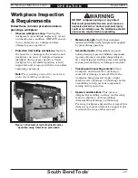
Страница 24: ...not be held liable for accidents caused by lack of training To reduce risk of eye injury from flying debris always wear safety glasses and a face shield when operating this machine NEVER exceed maximum rated pressure of press or machine damage and personal injury could occur Main Press 30 MPa 4350 PSI 60 Tons Side Press 17 MPa 2465 PSI 24 Tons Machine damage may occur if ram exerts maximum force w...

Страница 25: ...ress operation Verify workpiece has not shifted position is fully supported and is square with the ram before beginning operations Note Place padding around the machine to protect from falling workpieces Material strength Verify that workpiece material will fully withstand pressure applied by press during operation Assembled parts Disassemble any parts before pressing to prevent hidden components ...

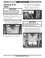
Страница 26: ...eam is lifted evenly see Figure 22 Remove support rods and raise press beam enough to allow support rods to be inserted into next set of placement holes Placement Placement Hole Hole Press Press Beam Beam Support Rod Support Rod 1 of 2 1 of 2 Adjusting Press Height It is important that the press be set to keep the workpiece as close to the ram as possible to ensure proper operation Adjusting Main ...

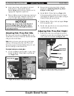
Страница 27: ... M12 1 75 hex bolt and repeat Steps 3 4 on opposite gib 5 Verify side press bed is secure and gib blocks are flush with press frame Adjusting Side Press Bed Gibs The side press bed gibs see Figure 23 can be adjusted to increase or decrease tension between side press bed and frame Note Always loosen side press bed gibs before raising or lowering side press bed This will help ease support rod instal...

Страница 28: ... an available link on lifting chain see Figure 26 5 Slowly raise side ram to apply tension to chain making sure bed is lifted evenly see Figure 26 Remove support rod and raise side press bed enough to allow support rod to be inserted into next set of placement holes 6 Lower side press bed onto support rod and extend ram to release chain tension Repeat Steps 5 6 until press bed is set at appropriat...

Страница 29: ...re gauges When the pressure for the current setting is reached the sound of the motor will change from a low pitched whine to a high pitched whine The reading on the pressure gauge will remain stationary signaling the regulator is bypassing the adjustment valve to maintain the current pressure Pressure Pressure Adjustment Adjustment Valve Valve Main Main Pressure Pressure Gauge Gauge Main Ram Main...

Страница 30: ...pressure adjustment valve clockwise to increase pressure or counterclockwise to decrease pressure 7 Once desired pressure is reached hold pressure adjustment valve in place and tighten jam nut Adjusting Pressure for Side Ram 1 Turn machine ON and verify no pressure is displayed on main pressure gauge 2 Adjust side press bed height see Adjusting Press Height on Page 24 to uppermost bed position and...

Страница 31: ... this design may require alternative support that is outside the scope of this manual To press a workpiece 1 Turn machine ON 2 Adjust press beam height so ram has enough space to extend and retract see Adjusting Press Height on Page 24 4 Press START button and move ram control lever to DOWN position to lower ram until it just touches workpiece see Figure 32 5 Ensure workpiece has not shifted posit...

Страница 32: ...A C C E S S O R I E S Accessories T20501 Face Shield Crown Protector 4 T20502 Face Shield Crown Protector 7 T20503 Face Shield Window T20451 Kirova Clear Safety Glasses T20452 Kirova Anti Reflective S Glasses T20456 DAKURA Safety Glasses T23963 ISO 32 Moly D Machine Oil 5 Gal Moly D oils are some of the best we have found for maintaining the critical components of machinery because they tend to re...

Страница 33: ...nsafe condition Weekly Lubricate ram cylinder track Check adjust hydraulic tank oil level Apply rust preventative to all cast iron surfaces Monthly Inspect lifting chain for wear Inspect press bed for wear damage Every 5 000 hours change hydraulic oil Protect the unpainted cast iron press bed by wiping it clean after every use this ensures moisture does not remain on bare metal surfaces Keep the b...

Страница 34: ...ns then every 5 000 hours thereafter Items Needed Qty Safety Glasses 1 Pair Face Shield 1 ISO 32 Hydraulic Oil 14 Gallons Funnel 1 Open End Wrench 17mm 1 15 Gallon Drain Pan 1 Clean Rags As Needed To change hydraulic oil 1 Reduce hydraulic pressure to 0 PSI see Adjusting Pressure for Main Ram on Page 28 2 DISCONNECT MACHINE FROM POWER 3 Position drain pan beneath hydraulic tank and remove fill cap...

Страница 35: ...lt 10 Test all legs for power replace if necessary 11 Wiring broken disconnected or corroded 11 Fix broken wires or disconnected corroded connections 12 START STOP or circuit breaker switch at fault 12 Replace switch circuit breaker 13 Motor or motor bearings at fault 13 Replace motor Machine has vibration or noisy operation 1 Motor or component loose 1 Replace damaged or missing bolts nuts or tig...

Страница 36: ... low for task 1 Adjust pressure adjustment valve to appropriate PSI for operation Page 27 2 Hydraulic system leaking 2 Locate source of leak and repair replace leaking part 3 Hydraulic filter clogged 3 Replace hydraulic filter 4 Obstruction in hydraulic line 4 Check hydraulic lines for obstructions 5 Pressure adjustment valve at fault 5 Replace pressure adjustment valve 6 Ram direction valve at fa...

Страница 37: ...results including serious injury or fire Motor Wiring The motor wiring shown in these diagrams is current at the time of printing but it may not match your machine Always use the wiring diagram inside the motor junction box Circuit Requirements Connecting the machine to an improperly sized circuit will greatly increase the risk of fire To minimize this risk only connect the machine to a power circ...

Страница 38: ... 2 2 2 Electrical Box 2 1 2 1 2 1 2 1 0 Door Limit Switch 2 4 Power Lamp Schneider XB2 BVB4LC Schneider XB2 BVB3LC Work Lamp Start Button Schneider ZB2 BE101C E STOP Button Schneider ZB2 BE102C Stop Button Schneider ZB2 BE102C Master Power Switch Schneider IECG0947 3 20A 690V 0 0 2 3 Motor 220V E E Ground Ground 4 2 2 U U Ground Motor Junction Box W2 U2 V2 U1 V1 W1 V2 U2 W2 W1 V1 U1 220 VAC 15 20 ...

Страница 39: ... Figure 40 Door limit switch Door limit switch Figure Figure 42 Motor junction box Motor junction box Figure Figure 41 Electrical box interior Electrical box interior South Bend Tools For Machines Mfd Since 12 20 Model SB1112 37 E L E C T R I C A L Electrical Components ...

Страница 40: ... 13 14 15 16 17 18 19 20 21 22 23 23 2 23 3 24 25 29 30 31 32 33 34 35 57 49 49 50 51 52 53 54 55 56 62 24 14 58 59 36 36 1 36 3 36 2 57 1 57 3 57 2 49 23 1 38 For Machines Mfd Since 12 20 South Bend Tools Model SB1112 P A R T S Main ...

Страница 41: ...ALVE PLATE 52 PSB1112052 MAIN BEAM 17 PSB1112017 BONDED SEALING WASHER 8MM 53 PSB1112053 CAP SCREW M8 1 25 X 20 18 PSB1112018 STRAIGHT FITTING M12 1 75 54 PSB1112054 HYDRAULIC HOSE ZMTE 2SN 400MM 19 PSB1112019 PRESSURE LINE 6MM CP 55 PSB1112055 HYDRAULIC HOSE ZMTE 2SN 700MM 20 PSB1112020 E STOP BUTTON SCHNEIDER ZB2 BE102C 56 PSB1112056 HYDRAULIC HOSE ZMTE 2SN 3400MM 21 PSB1112021 PHLP HD SCR M3 5 ...

Страница 42: ... 204 205 206 207 208 209 210 211 212 213 214 214 1 214 2 214 3 214 4 215 216 217 218 219 220 221 222 223 224 224 1 224 2 224 3 40 For Machines Mfd Since 12 20 South Bend Tools Model SB1112 P A R T S Hydraulic Pump ...

Страница 43: ...ONTROL VALVE BTA 2 POS 208 PSB1112208 COUPLER BLOCK 220 PSB1112220 DIRECTIONAL CONTROL VALVE BTA 3 POS 209 PSB1112209 MOTOR COUPLER 221 PSB1112221 PRESSURE ADJUSTMENT VALVE 210 PSB1112210 MOTOR SUPPORT 222 PSB1112222 OIL FILTER 211 PSB1112211 LOCK WASHER 10MM 223 PSB1112223 SIGHT GLASS M42 1 5 212 PSB1112212 FLAT WASHER 10MM 224 PSB1112224 CONTROL HANDLE ASSEMBLY 213 PSB1112213 HEX BOLT M10 1 5 X ...

Страница 44: ...302 302 303 304 305 306 307 308 309 310 311 312 313 314 315 316 317 318 37 38 39 40 41 42 43 44 45 46 47 48 63 64 46 48 42 For Machines Mfd Since 12 20 South Bend Tools Model SB1112 P A R T S Main Ram Cylinder ...

Страница 45: ... X 160 44 PSB1112044 FLAT WASHER 12MM 310 PSB1112310 O RING 3 1 X 50 45 PSB1112045 HANDLE ROD M12 1 75 311 PSB1112311 PISTON ROD 46 PSB1112046 HANDLE SEAT 312 PSB1112312 CYLINDER END 47 PSB1112047 ROLL PIN 5 X 24 313 PSB1112313 O RING 3 1 X 160 48 PSB1112048 FIXED HANDLE 16 X 88 M12 1 75 X 10 314 PSB1112314 GUIDANCE TAPE 20 X 3 X 165 63 PSB1112063 SET SCREW M5 8 X 15 DOG PT 315 PSB1112315 O RING 5...

Страница 46: ...26 27 28 401 401 402 402 403 404 405 406 407 408 409 410 411 412 413 414 415 416 417 418 419 44 For Machines Mfd Since 12 20 South Bend Tools Model SB1112 P A R T S Side Ram Cylinder ...

Страница 47: ...SB1112402 FLAT WASHER 14MM 413 PSB1112413 O RING 3 1 X 100 403 PSB1112403 CYLINDER BARREL 414 PSB1112414 CYLINDER END 404 PSB1112404 UPPER LOCK RING 415 PSB1112415 GUIDANCE TAPE 15 X 2 5 X 154 405 PSB1112405 FLAT WASHER 20MM 416 PSB1112416 LOWER LOCK RING 406 PSB1112406 PISTON 417 PSB1112417 O RING 3 5 X 56 407 PSB1112407 SEAL D100 418 PSB1112418 SCRAPER SEAL 50MM 408 PSB1112408 RETAINING RING 419...

Страница 48: ...ENGEN YBLXW 5 11Q1 Contactor OL Relay 501 500 511 512 510 509 508 505 502 503 507 506 504 REF PART DESCRIPTION REF PART DESCRIPTION 500 PSB1112500 MASTER POWER SWITCH SCHNEIDER 20A 507 PSB1112507 OL RELAY SCHNEIDER LRD21C 12 18A 501 PSB1112501 START BUTTON SCHNEIDER ZB2 BE101C 508 PSB1112508 CIRCUIT BREAKER SCHNEIDER D2 400V 502 PSB1112502 STOP BUTTON SCHNEIDER ZB2 BE102C 509 PSB1112509 CIRCUIT BR...

Страница 49: ...112603 MASTER ON OFF LABEL 616 PSB1112616 BIOHAZARD LABEL 604 PSB1112604 KEEP PANEL CLOSED LABEL 617 PSB1112617 REPLACE HYDRAULIC OIL LABEL 605 PSB1112605 QR CODE LABEL 618 PSB1112618 SOUTH BEND NAMEPLATE 203MM 606 PSB1112606 START BUTTON LABEL 619 PSB1112619 RELEASE PRESSURE LABEL 607 PSB1112607 STOP BUTTON LABEL 620 PSB1112620 TOUCH UP PAINT SB GRAY 608 PSB1112608 EMERGENCY STOP BUTTON LABEL 621...

Страница 50: ...UGE DIRECTIONAL CONTROL VALVE DIRECTIONAL CONTROL VALVE MAIN RAM CYLINDER SIDE RAM CYLINDER DIRECTIONAL CONTROL VALVE MOTOR 220V PRESSURE ADJUSTMENT VALVE T P T P A B A B 48 For Machines Mfd Since 12 20 South Bend Tools Model SB1112 A P P E N D I X Hydraulic Diagram ...

Страница 51: ...omestic or foreign government industry or authority In no event shall South Bend s liability under this warranty exceed the original purchase price paid for this machine Any legal actions brought against South Bend Tools shall be tried in the State of Washington County of Whatcom This is the sole written warranty for this machine Any and all warranties that may be implied by law including any merc...

Страница 52: ...southbendtools com Printed In China KS21377 ...

Отзывы: