

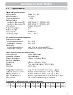


17
Operation
E.1
Display and Input
Display symbols:
Pump
(rotates in operation)
Valve
(direction of fl ow black)
Collector
Storage tank
Solid fuel boiler
Swimming pool
Temperature sensor
Thermostat On / Off
Warning / error message
New information available
(1)
(2)
(3)
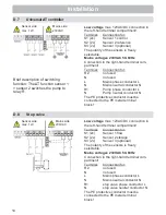
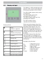
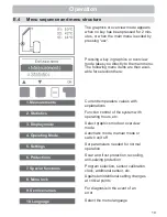
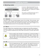
The display (1), with its extensive text and
graphics mode, is almost self-explanatory,
allowing easy operation of the controller.
The LED (2) lights up green when a relay
is switched on.
The LED (2) lights up red when
operating mode “Off” is set.
The LED (2) fl ashes slowly red in the
operating mode “Manual”.
The LED (2) fl ashes quickly
red when an error is present.
Entries are made using four keys (3+4),
which are assigned to different functions
depending on the situation. The “esc”
key (3) is used to cancel an entry or to
exit a menu. If applicable there will be a
request for confi rmation as to whether the
changes which have been made should
be saved.
The function of each of the other three
keys (4) is shown in the display line di-
rectly above the keys; the right-hand key
is generally has a confi rmation and selec-
tion function.
Examples of key functions:
+/-
= enlarge/shrink values
▼
/
▲
= scroll menu down/up
yes/no
= approve/reject
Info
= additional information
Back
= to previous screen
ok
= confi rm selection
Confi rm
= confi rm setting
E.1
Display and input


