


1-26
VPH-G90E/G90U/G90M
Installation/connection examples
Installation/connection examples
51
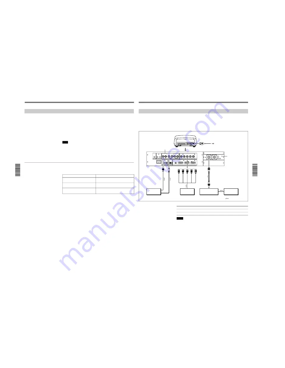
Using the PC-1271/1271M Signal Interface Switcher
When you install the optional IFB-40 Signal Interface Board to the
projector and connect the PC-1271/1271M Signal Interface Switcher to the
IFB-40, you can connect easily various input sources.
You can select the input to the switcher easily by pressing the
SWITCHER/VIDEO MEMORY/INDEX keys on the remote commander.
Choose the appropriate cable from the following table.
1 m
2 m
5 m
10 m
15 m
25 m
50 m
—
CCQ-2BRS CCQ-5BRS CCQ-10BRS —
CCQ-25BRS CCQ-50BRS
SIC-M-1
—
SIC-M-5
—
SIC-M-15
SIC-M-25
SIC-M-50
Notes
• Insert the female and male plugs of the SIC-M or CCQ-BRS cable
correctly.
• You can extend the SIC-M or CCQ-BRS cable up to 50 m.
• The video signal input to the IFB-40 installed to the INPUT B section
should not exceed 70 MHz. When projecting the video signal which
exceeds 70 MHz, connect the signal source to the INPUT A connectors
using the 5BNC cables.
Setting up
• Set INPUT-A in the SET SETTING 1 menu
(page 38)
to RGB.
• Select VIDEO or S VIDEO by pressing the INPUT SELECT keys on the
remote commander.
• Set the SINGLE/SECOND/OTHER select switch on the switcher to
SINGLE.
TRIGGER
LINK
S VIDEO
OUT
IN
C IN
Y IN
VIDEO
VIDEO
R-Y/PR
R
B-Y/PB
G
B
SYNC/HD
VD
INPUT A
Y
CONTROL S
PLUG IN POWER
DEVICE INDEX
IN
OUT
IN
OUT
IN
OUT
REMOTE
RS-232C/422A
RS-232C RS-422A
IN
OUT
PJ COM
IN
OUT
MODE
REMOTE1
to REMOTE 1 OUT
SIC-M or CCQ-BRS
connecting cable
Rear
PC-1271/1271M
Switcher
Video
equipment
Video
equipment
Computer
AC power cord (supplied)
to a wall outlet
R
G
B
SYNC/HD
VD
to RGB output
to video output
to S Video output
VIDEO IN
IFB-40 Signal
Interface Board
(optional)
IN
S VIDEO
IN
AC IN
Signal flow
INPUT A
*
For the VPH-G90E model : IFB-G90E Video Interface Board (optional)
*
Installation/connection examples
50
Installation/connection examples
Connection Examples
Confirming the System Construction
After all the connections are complete, confirm that equipment of the
system is properly setup.
1
Connect the AC power cords of all equipment to the AC outlets.
2
Press the SYS SET key on the remote commander or the control panel.
Information on the system construction and the settings of the interface
boards, etc. are automatically confirmed. Then the message disappears.
Note
When you want to use the projector without connecting the switcher after
using the switcher in the system connections, it is necessary to confirm the
system construction again by pressing the SYS SET key after all the
connections are complete. If you press the key, “Master Switcher not exit”
appears, but the system construction is automatically recognized.
When a system error is detected
The following messages are displayed on the screen.
Message
Master Switcher not exist.
Same DEVICE INDEX for Projector
detected.
Same DEVICE INDEX for Switcher
detected.
Remedy
Set the switcher that outputs the signal to
the projector to number 1.
Change either number of the projectors
that have the same number.
Change either number of the switchers
that have the same number.
Содержание VPH-G90E
Страница 10: ......
Страница 120: ......
Страница 122: ...2 2 VPH G90E G90U G90M 2 1 3 Location 3 ME MB MC PB M L MA BA F BC NA BB ...
Страница 128: ...2 8 VPH G90E G90U G90M 2 2 8 Remote Commander Removal 1 Two screws BVTP 3 x 12 2 Remote commander A CN1 ...
Страница 144: ...2 24 VPH G90E G90U G90M XA board A 1390 918 A XB board A 1390 919 A XC board A 1501 447 A 2 2 25 Extension Board ...
Страница 190: ......
Страница 204: ......
Страница 210: ......
Страница 224: ......
Страница 337: ...9 1 9 1 VPH G90E G90U G90M SECTION 9 BLOCK DIAGRAMS ...
Страница 363: ...2 3 4 5 A B C D E F G H 1 10 1 10 1 VPH G90J G90E G90U G90M SECTION 10 DIAGRAMS ...
Страница 408: ...2 3 4 5 A B C D E F G H 1 10 46 10 46 VPH G90J G90E G90U G90M BC BC BC BOARD BC A SIDE SUFFIX 11 BC B SIDE SUFFIX 11 ...
Страница 437: ...2 3 4 5 A B C D E F G H 1 10 75 10 75 VPH G90J G90E G90U G90M ...
Страница 438: ...2 3 4 5 A B C D E F G H 1 10 76 10 76 VPH G90J G90E G90U G90M DC A SIDE SUFFIX 11 DC DC DC BOARD ...
Страница 439: ...2 3 4 5 A B C D E F G H 1 10 77 10 77 VPH G90J G90E G90U G90M DC DC DC BOARD DC B SIDE SUFFIX 11 ...
Страница 462: ...2 3 4 5 A B C D E F G H 1 10 100 10 100 VPH G90J G90E G90U G90M E A SIDE SUFFIX 11 E E E BOARD ...
Страница 463: ...2 3 4 5 A B C D E F G H 1 10 101 10 101 VPH G90J G90E G90U G90M E E E BOARD E B SIDE SUFFIX 11 ...
Страница 474: ...2 3 4 5 A B C D E F G H 1 10 112 10 112 VPH G90J G90E G90U G90M ...
Страница 516: ...2 3 4 5 A B C D E F G H 1 10 154 10 154 VPH G90J G90E G90U G90M F F F BOARD F A SIDE SUFFIX 11 F B SIDE SUFFIX 11 ...
Страница 518: ...2 3 4 5 A B C D E F G H 1 10 156 10 156 VPH G90J G90E G90U G90M GA GA GA BOARD GA A SIDE SUFFIX 11 ...
Страница 519: ...2 3 4 5 A B C D E F G H 1 10 157 10 157 VPH G90J G90E G90U G90M GA GA GA BOARD GA B SIDE SUFFIX 11 ...
Страница 522: ...2 3 4 5 A B C D E F G H 1 10 160 10 160 VPH G90J G90E G90U G90M GB GB GB BOARD GB A SIDE SUFFIX 11 ...
Страница 523: ...2 3 4 5 A B C D E F G H 1 10 161 10 161 VPH G90J G90E G90U G90M GB GB GB BOARD GB B SIDE SUFFIX 11 ...
Страница 530: ...2 3 4 5 A B C D E F G H 1 10 168 10 168 VPH G90J G90E G90U G90M GC GC GC BOARD GC A SIDE SUFFIX 11 GC B SIDE SUFFIX 11 ...
Страница 532: ...2 3 4 5 A B C D E F G H 1 10 170 10 170 VPH G90J G90E G90U G90M M M M BOARD M A SIDE SUFFIX 11 ...
Страница 533: ...2 3 4 5 A B C D E F G H 1 10 171 10 171 VPH G90J G90E G90U G90M M M M BOARD M B SIDE SUFFIX 11 ...
Страница 537: ...2 3 4 5 A B C D E F G H 1 10 175 10 175 VPH G90J G90E G90U G90M MA MA MA BOARD MA A SIDE SUFFIX 11 MA B SIDE SUFFIX 11 ...
Страница 546: ...English 98LT0812 1 Printed in Japan 1998 12 9 929 608 01 Sony Corporation Broadcasting Professional Systems Company ...


