7
Locations and Functions
of Parts
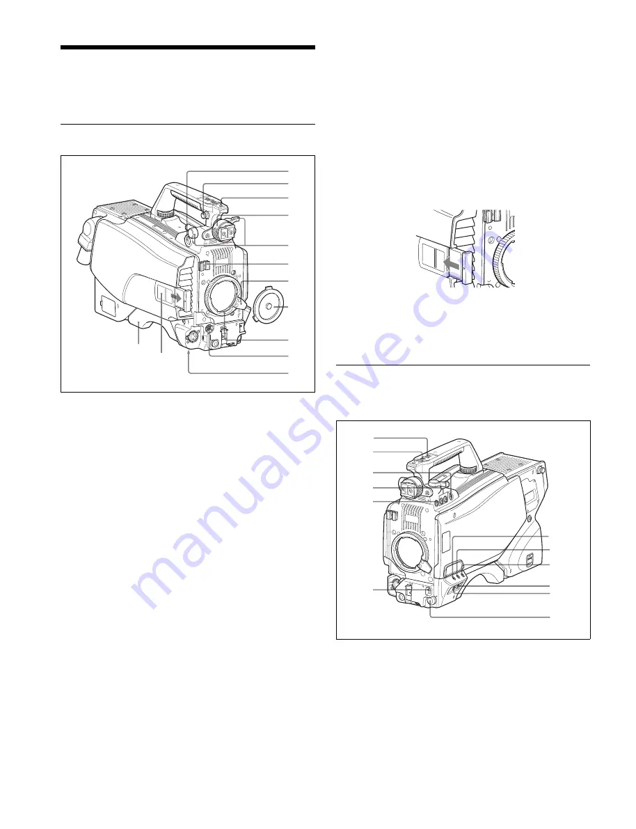
Accessory Attachments
a
VF (viewfinder) connector (20-pin)
Connect the cable of the viewfinder (not supplied).
b
Shoulder strap fitting post
Attach one end of a shoulder strap (not supplied) to this fitting
post, and the other end to the fitting post on the other side of
the camera.
c
Accessory shoe
To attach an accessory using a 1/4-inch screw.
d
Viewfinder left-right positioning ring
Locks the left-right position of the viewfinder.
Loosen this ring to adjust the viewfinder position.
e
Viewfinder front-rear positioning lever and LOCK knob
Locks the front-rear position of the viewfinder.
Loosen the lever and knob to adjust the viewfinder position.
For details about adjusting the viewfinder position, see
“Attaching a Viewfinder” on page 14.
f
Lens cable clamp
To secure the cable of the lens (not supplied).
g
Lens fixing lever
To secure the lens in the lens mount.
h
Lens mount cap
Always keep the lens mount covered with this cap when a lens
is not attached. The cover can be removed by moving the lens
fixing lever upwards.
i
Lens mount
To attach a lens.
j
LENS connector (12-pin)
Connect the lens cable. The camera can control the lens
functions through this cable.
k
Tripod mount
Attach the VCT-14 Tripod Attachment when mounting the
camera on a tripod.
l
Camera number
Insert the supplied camera number label to display the camera
number.
m
Shoulder pad
You can adjust the position toward the front or rear.
For details, see “Adjusting the Shoulder Pad Position” on
page 17.
Controls and Connectors
Front right
a
INCOM (intercom 1) button
The intercom 1 microphone is turned ON while this button is
held pressed.
You can also assign other functions to this button, using the
menu displayed on the viewfinder screen.
b
d
e
f
g
h
i
j
k
l
a
c
m
b
c
d
e
f
g
h
i
j
k
a
l


