


87
STR-DA2000ES/DB2000
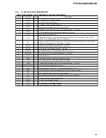
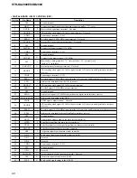
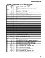
Pin No.
Pin Name
I/O
Description
45
NC
I
Not used
46
DIR-CE
O
Chip enable signal output to the digital audio interface receiver
47
DIR-DO
I
Read data input from the digital audio interface receiver
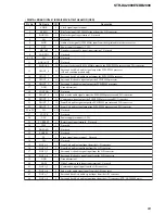
48
NC
I
Not used
49
DIR-DI
O
Write data output to the digital audio interface receiver
50
CLKSW
O
Analog/digital selection signal output terminal “L”: analog, “H”: digital
51
NC
I
Not used
52
MD2
I
Setting terminal for the CPU operation mode Fixed at “L” in this set
53
MD1
I
Setting terminal for the CPU operation mode Fixed at “H” in this set
54
MD0
I
Setting terminal for the CPU operation mode Fixed at “L” in this set
55
RSTX
I
System reset signal input from the reset signal generator “L”: reset
For several hundreds msec. after the power supply rises, “L” is input, then it changes to “H”
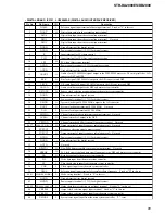
56
VCC
—
Power supply terminal (+3.3V)
57
X1
O
Main system clock output terminal (16.5 MHz)
58
X0
I
Main system clock input terminal (16.5 MHz)
59
VSS
—
Ground terminal
60
STOP
I
AC off detection signal input terminal
61
RDS-CLK
I
RDS interrupt clock signal input from the tuner unit (STR-DB2000: AEP and UK models only)
62
POW-SW
I
I/
1
key input terminal “L”: power on
63
CTL-A1IN
I
Sircs signal input for CTRL A1II
64
NC
I
Not used
65
PRE-RY
O
Relay drive signal (for pre out and sub woofer) output terminal “H”: relay on
(Pre out: STR-DA2000ES only)
66
SIRCS
I
Sircs signal input terminal
67
NC
I
Not used
68
VCC
—
Power supply terminal (+3.3V)
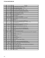
69
PCM-FAINT
O
PCM imitation signal output terminal
70
DSP-HACN
I
Acknowledge signal input from the DSP
71
DSP-HDIN
O
Serial data output to the DSP
72
DSP-HCLK
O
Serial data transfer clock signal output to the DSP
73
DSP-HDOUT
I
Serial data input from the DSP
74
DSP-HCS
O
Chip select signal output to the DSP
75
DSP-GP12
O
Write signal output to the DSP
76
DSP-BST
O
Boot strap signal output to the DSP
77
VCC
—
Power supply terminal (+3.3V)
78
DSP-XRST
O
System reset signal output to the DSP “L”: reset
79
DSP-PM
O
PLL initialize signal output to the DSP
80
DSP-GP9
I
Read ready signal input from the DSP
81
DSP-BSTSEL
O
Signal selection signal output terminal “L”: boot strap signal, “H”: L/R sampling clock signal
82
NC
I
Not used
83
SUBU-RST
O
Reset signal output to the sub system controller and DC cut digital filter “L”: reset
84
SUBU-MUTE
O
Muting on/off control signal output terminal Not used
85
SUBU-CTRL
O
Clock signal output to the sub system controller
86
SUBU-INFO2
I
Serial data input from the sub system controller
87
SUBU-INFO1
O
Serial data output to the sub system controller
88
CTRL-A1
O
Sircs signal output for CTRL A1II
Содержание STR-DA2000ES - Fm Stereo/fm-am Receiver
Страница 152: ...STR DA2000ES DB2000 12 12 MEMO ...


