


SERVICE MANUAL
STR-DA2000ES/DB2000
1
Ver 1.1 2003.12
SUPPLEMENT-1
Subject: Change of CIS, DISPLAY, FUNCTION, HP-V3,
REG, S-VIDEO, TH and VOL boards
(ECN-TAC12992)
9-961-061-81
STR-DA2000ES/DB2000
US Model
Canadian Model
STR-DA2000ES
AEP Model
UK Model
E Model
STR-DB2000
• NEW/FORMER TYPE DESCRIPTION
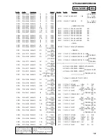
New/former type of the CIS, DISPLAY, FUNCTION, HP-V3, REG, S-VIDEO, TH and VOL boards is discriminated by difference of the
pattern.
JW914
JW917
JW922
JW923
JW924
Q909
C907
R908
C905
JW961
R905
R922
R928
R927
JW960
JW925
JW918
JW921
R917
R909
R916
Q908
R915
Q906
Q910
R914
D906
R906
R921
Q905
IC903
R918
4
1
1-688-603-
11
(12)
D
E
E
C
B
E
E
JW914
JW917
JW922
JW923
JW924
Q909
C907
R908
C905
JW961
R905
R922
R928
R927
JW960
JW925
JW918
JW921
R917
R909
R916
Q908
R915
Q906
Q01
R914
D906
R906
R921
Q905
IC903
R918
4
1
1-688-603-
11
(11)
D
E
E
C
B
E
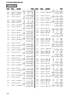
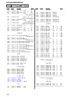
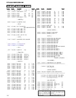
– REG BOARD (Conductor Side) –
Former type
New type
%
%
1.
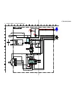
DIAGRAMS
1-1.
NOTE FOR PRINTED WIRING BOARDS AND SCHEMATIC DIAGRAMS
Note on Printed Wiring Boards:
•
X
: parts extracted from the component side.
•
Y
: parts extracted from the conductor side.
•
f
: internal component.
•
: Pattern from the side which enables seeing.
(The other layers' patterns are not indicated.)
• Indication of transistor.
C
B
These are omitted.
E
Q
B
These are omitted.
C
E
Q
B
These are omitted.
C
E
Q
Note on Schematic Diagram:
• All capacitors are in
µ
F unless otherwise noted. pF:
µµ
F
50 WV or less are not indicated except for electrolytics
and tantalums.
• All resistors are in
Ω
and
1
/
4
W or less unless otherwise
specified.
•
f
: internal component.
•
2
: nonflammable resistor.
•
C
: panel designation.
Caution:
Pattern face side:
Parts on the pattern face side seen from
(Conductor Side)
the pattern face are indicated.
Parts face side:
Parts on the parts face side seen from
(Component Side) the parts face are indicated.
•
A
: B+ Line.
•
B
: B– Line.
• Voltages are taken with a VOM (Input impedance 10 M
Ω
).
Voltage variations may be noted due to normal produc-
tion tolerances.
• Signal path.
f
: TUNER
F
: AUDIO (ANALOG)
J
: AUDIO (DIGITAL)
E
: VIDEO
Note:
The components identi-
fied by mark
0
or dotted
line with mark
0
are criti-
cal for safety.
Replace only with part
number specified.
Note:
Les composants identifiés par
une marque
0
sont critiques
pour la sécurité.
Ne les remplacer que par une
pièce por tant le numéro
spécifié.
Содержание STR-DA2000ES - Fm Stereo/fm-am Receiver
Страница 152: ...STR DA2000ES DB2000 12 12 MEMO ...


