


86
STR-DA2000ES/DB2000
•
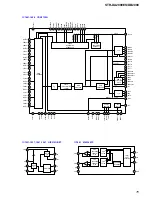
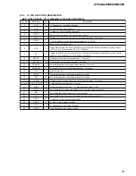
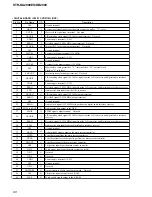
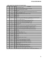
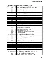
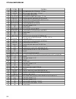
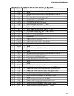
DIGITAL BOARD IC2601 MB91F155A-3B9-X100 (MAIN SYSTEM CONTROLLER)
Pin No.
Pin Name
I/O
Description
1
MENU –JOG
I
Jog dial pulse input from the rotary encoder (B phase input) (for MENU)
2
MENU +JOG
I
Jog dial pulse input from the rotary encoder (A phase input) (for MENU)
3
+/– –JOG
I
Jog dial pulse input from the rotary encoder (B phase input) (for –/+)
4
+/– +JOG
I
Jog dial pulse input from the rotary encoder (A phase input) (for –/+)
5
FUNC –JOG
I
Jog dial pulse input from the rotary encoder (B phase input) (for INPUT SELECTOR)
6
FUNC +JOG
I
Jog dial pulse input from the rotary encoder (A phase input) (for INPUT SELECTOR)
7
VOL –JOG
I
Jog dial pulse input from the rotary encoder (B phase input) (for MASTER VOLUME)
8
VOL +JOG
I
Jog dial pulse input from the rotary encoder (A phase input) (for MASTER VOLUME)
9
VSS
—
Ground terminal
10
FL_CLK
O
Serial data transfer clock signal output to the fluorescent indicator tube driver
11
FL_DATA
O
Serial data output to the fluorescent indicator tube driver
12
FL_LAT
O
Chip select signal output to the fluorescent indicator tube driver
13
FL_RST
O
Reset signal output to the fluorescent indicator tube driver “L”: reset
14
ML_CH_DEC-LED
O
LED drive signal output of the MULTI CANNEL DECODING indicator “H”: LED on
15
HP-SW
I
Headphone detection signal input terminal “H”: headphone is connected
16
DIMMER
O
Dimmer on/off control signal output terminal “L”: dimmer on
17
2ND-RY
O
Relay drive signal (for 2nd zone out) output terminal “H”: relay on
(STR-DA2000ES only)
18
POW-RY
I
Relay drive signal (for main power) output terminal “H”: relay on
19
TU-TUNED
I
Tuned detection signal input from the tuner unit
20
TU-MUTE
O
Muting request control signal output to the tuner unit
21
SERIAL-DATA
O
Serial data output to the function switch, electrical volume and tuner unit
22
SERIAL-CLK
O
Serial data transfer clock signal output to the function switch, electrical volume and tuner unit
23
TU-DATAIN
I
Serial data input from the tuner unit
24
TU-STEREO
I
FM stereo detection signal input from the tuner unit
25
RDS-DATA
I
RDS serial data input from the tuner unit (STR-DB2000: AEP and UK models only)
26
VSS
—
Ground terminal
27
VCC
—
Power supply terminal (+3.3V)
28
TU-LAT
O
Serial data latch pulse signal output to the tuner unit
29
FUNC_SW-LAT
O
Serial data latch pulse signal output to the function switch
30
VOL-LAT
O
Serial data latch pulse signal output to the electrical volume
31
MLT_D.MIX-LAT
O
Serial data latch pulse signal output to the function switch
32
SYS-MUTE
O
System muting on/off control signal output terminal “L”: muting on
33
POW-CHANGE
O
Tuner auto stop signal output terminal
34
V-POW
O
Video section power on/off control signal output terminal “H”: power on
35
NC
I
Not used
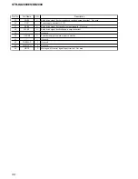
36, 37
SELB OPT,
SELA OPT
O
Digital input selection signal output terminal
38
DIR-ERROR
I
PLL lock error signal and data error flag input from the digital audio interface receiver
39
DIR-XSTATE
I
Source clock selection monitor input from the digital audio interface receiver
40
DIR-DATA0
I
Audio serial data input from the digital audio interface receiver
41
DIR-XMODE
O
System reset signal output to the digital audio interface receiver “L”: reset
42
DIR-CKSEL1
O
Output clock selection signal output to the digital audio interface receiver
43
DIR-CLK
O
Clock signal output to the digital audio interface receiver
44
VSS
—
Ground terminal
Содержание STR-DA2000ES - Fm Stereo/fm-am Receiver
Страница 152: ...STR DA2000ES DB2000 12 12 MEMO ...


