19
D-FS18
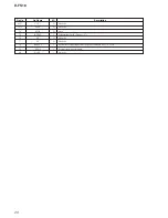
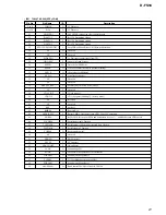
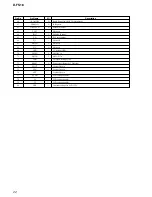
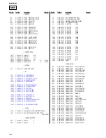
5-9. IC PIN FUNCTION DESCRIPTION
• IC801 TMP88CM22R-SFMP1 (SYSTEM CONTROLLER)
Pin No.
1
2
3
4
5
6
7
8
9
10
11
12
13
14
15
16
17
18
19
20
21
22
23
24
25
26
27
28
29
30
31
32
33
34
35
36
37
38
39
40
41
42
43
44
45
46
47
48
49-64
65-68
I/O
—
—
I
O
O
O
O
O
O
O
I
O
O
I
I
I
I
I
I
I
I
I
I
—
I
I
I
O
O
O
I
O
O
O
I
I
I
I
I
I
O
O
O
O
O
O
O
O
O
O
Description
Ground terminal.
Headphone IC power switch.
Focus OK signal input from the digital servo processor (IC601). “L”:NG,”H”:OK
AGC control puls signal output terminal.
CD mode on.
tuner power block on.(Supply vin)
Analog audio muting ON/OFF control signal output terminal. “H”:muting ON
VCC2 voltage control signal output terminal.
Reset signal output to IC601. “L”:reset
Serial data transfer clock signal output to IC601.
Serial data input from the IC601.
Serial data output to IC601.
WAKE-UP control signal output terminal. (for system standby reset)
Plug-in detection signal input terminal of LINE OUT/OPTICAL OUT.
Batery charge voltage detection input from the power control(IC401).
Not used.
Batery voltage monitor signal input .
Main switch unit kye AD port.
Acknowledgement and status from DTS.
DC in voltage monitor signal input.
Upper lid ststus signal input.
Analog GND for A/D signal input.
Analog VDD for A/D signal input.
Power supply te2V).
Sub-code sync(S0+S1)detection signal input from the IC601.
GRSCOR signal input from the IC601.
H-MIRX series, L-MISX
Beep sound output to the headphone amplifier(IC302).
DTS pull up 200K.
Communication clock output to the communication format converter (IC802).
Serial data out to DTS.
Serial data in to DTS.
LCD buty data send request signal output.
Radio mode status signal output.
H-CD RW disc enabled , L-disabled.
ADPCM compression on sigunal inout.
Not used.
Automatic volume limit system.
HOLD switch detection signal input.
Not usde.
Signal cell battery detection sigunal output.
Optical pick-up power ON/OFF control signal output terminal. “L”:ON.
Serial data latch pulse signal output to IC601.
Serial data output enable signal output terminal.
Audio channel selection. (Raidio/CD music)
Latch signal output to the power control(IC401).
Audio channel selection. (Raidio/CD music)
APC mute signal output terminal. “L”:mute
LCD segment signal output.
Not usde.
Pin Name
VSS
HPSW
FOK I
AGCPWM O
CDON O
TU PWSWEN O
AMUTE O
VCC2ON O
XRST O
SCK O
SCK O
MSDTO O
WAKEUP O
AD CDTEST
AD CHGMNT
RESERVE
AD BATMNT
AD CDKEY
ACK CD I
AD DCINMNT
WP OPEN
VREFL
VREFH
VDD
SCOR I
GRSCOR I
MIR I
BEEP O
XCDRESET TU O
TUSCK O
SDI I
SDO O
LCDREQ
TUON I
CD RW I
COMPON I
DIG TU I
AVLS I
HOLD I
EXBATT I
BATDET
XHGON O
XLAT O
XSOE O
CDAUDIO O
XPOWLT O
TUAUDIO O
XAPC OFF O
SEG15-SEG0
COM3-COM0
Содержание Sports D-FS18
Страница 7: ...7 D FS18 1 4 5 3 2 Lid Upper Switch unit Five screws B 1 7 3 5 Cover Lid 3 5 LID UPPER SWITCH UNIT ...
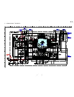
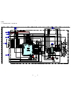
Страница 14: ...14 14 D FS18 5 4 SCHEMATIC DIAGRAM TUNER SECTION IC B D ...
Страница 15: ...15 15 D FS18 5 5 SCHEMATIC DIAGRAM CD SECTION 1 4 ...
Страница 16: ...16 16 D FS18 5 6 SCHEMATIC DIAGRAM CD SECTION 2 4 IC B D ...
Страница 17: ...17 17 D FS18 5 7 SCHEMATIC DIAGRAM CD SECTION 3 4 IC B D ...
Страница 18: ...18 18 D FS18 5 8 SCHEMATIC DIAGRAM CD SECTION 4 4 IC B D ...


