5-4E
1
2
3
4
5
6
7
8
9
10
11
12
13
14
15
16
17
18
19
20
21
22
23
24
25
26
27
28
29
30
47
48
49
50
51
52
53
54
55
56
–
–
I/O
I/O
I
I
O
I
I
–
I/O
I/O
I/O
I/O
I
I
I
O
–
O
I
–
I
I
I
I
I
I
–
–
–
O
O
O
O
O
I
I
I
Servo ground
Analog ground
CTL Head signal input/output (REC mode)
CTL Head signal input/output (REC mode)
CTL amp. control signal input (gain set)
CTL amp. control signal input (gain set)
CTL amp. control signal input (for check)
CTL amp. control signal input (gain set)
Capstan FG schmitt input
Power supply unswitch 5V
AFC oscillation signal
AFC oscillation signal
AFC LPF signal
Sync input
VLPF input
Composite video signal input 2
Composite video signal input 1
Power supply OSD 5V
Composite video signal output
OSD ground
OSC 4fsc oscillator terminal signal output
OSC 4fsc oscillator terminal signal input
Analog ground
APC error voltage signal input
Auto tuning signal input
Function key analog voltage signal input 2
Function key analog voltage signal input 2
Power failure detect signal input
Destination set signal input 1
Not used
Destination set signal input 2
Take up end sensor signal input
Supply end sensor signal input
Video RF envelope signal
Audio RF envelope signal
Analog power supply
Mechanism Section CAM encoder data input 1
Mechanism Section CAM encoder data input 2
Mechanism Section CAM encoder data input 3
Mechanism Section CAM encoder data input 4
S side reel FG input
T side reel FG input
Remote Control (SIRCS) signal input
CTL amp. signal input/output (OSD)
CAM motor signal output
Not used
Not used
Not used
Top/end LED on/off control signal output
Power supply control signal output
EEP ROM write timing control signal output
OSD block control output
To 'on' the audio dub filter
Easy Timer knob pulse 1 signal input
Easy Timer knob pulse 2 signal input
Power supply
VSS (SERVO)
AN GND
CTL(+)
CTL (–)
CTL-BIAS
CTL-FB
CTL-AMP(O)
CTL-SMT
CAP FG
VCC (SERVO)
AFC PC
AFC OSC
AFCLPF
CSYNC
VLPF
C V IN 2
C V IN 1
OSDVSS
VIDEO OUT (CV OUT)
OSD VSS
4FSC OUT
4Ffsc IN
AVSS
APC Error
TU AFT
FUNCTION Key 2
FUNCTION Key 1
POWER FAIL
DEST 1
PB
RR LED
SEARCH LED
END LED
POWER CONT
WRITE CONT
BLUE BACK
AUDIO DUB
ETR 1
ETR 2
VCC
Pin No.
Pin Name
I/O
Function
57
58
59
60
61
62
63
64
65
66
67
68
69
70
71
72
73
74
75
76
77
78
79
80
81
82
83
84
85
86
87
88
89
90
91
92
93
94
95
96
97
98
99
100
101
102
103
104
105
106
107
108
109
110
111
112
–
–
I/O
I/O
I/O
I/O
I/O
O
I
O
O
O
O
–
O
O
O
I
O
I
I
I
–
O
–
I
–
O
O
I
–
–
O
O
O
O
O
O
O
O
O
–
–
I
–
I
I
I
O
O
O
O
O
–
I
–
Ground
FLD ground
Clock signal input/output
Data input/output for IIC
Clock input/output for IIC bus interface
Data input/output for IIC bus interface
SCI clock input/output
Serial communication data signal output
Serial communication data signal input
Tuner audio mute
Force mono
Bilingual select
Stereo/mono control
Not used (only for secam model)
Full erase head on/off control signal
"L" : output when REC pause
Line-input selection control signal output
Enables flash write
Timer clock terminal (32khz) output
Timer clock terminal (32khz) input
Reset signal output
System clock terminal (10MHz) input
Ground
System clock terminal (10MHz) input
Smoothing capacitor connection
Sets operating mode
Not used
APC PWM signal output
Capstan TRQ PWM signal output
Erasing protection tab. Cassette in detection signal input
Not used
Not used
"H" : audio mute signal output
Capstan reverse control signal "H": when reverse
Capstan step driving signal output
Drum motor step driving signal output
Tuner PLL clock signal output
Tuner PLL chip select signal output
Tuner PLL data signal output
Normal audio PB signal output
"L": output when Hi-Fi audio REC pause (not used)
Not used
Not used
To detect type of color system
Not used
To detect mesecam signal
Drum FG schmitt amp. input
Drum FG schmitt amp. put
RF switching pulse signal output
AF switching pulse signal output
Drum motor error signal output
Capstan error signal output
Quasi VD pulse signal output
Ground
Composite sync signal input
Power supply unswitch 5V
VSS
FLD VSS
SCL0
SDA0
SCL1
SDA1
SCK1
SO1
SI1
TA MUTE
F MONO
MAIN SAP
STEREO OUT
SECAM ON
FULL ERASE
REC P
IN SELECT
FLASH WRITE ENABLE
32KHZ (OUT)
32KHZ (IN)
RESET
10MHZ (IN)
VSS
10MHZ (OUT)
CAP CONNET TO VSS
MDO
TV/VTR
APC PWM
CAP TRQ PWM
REC PROOF
NIL
NIL
A MUTE
CAP RVS
CAP QR
DRUM QR
PLL CLOCK
TU ENABLE
PLL DATA
NA PB
AF REC P
EX CTL
SECAM DET
C. KILLER DET
HEAD CLOG LED
MESECAM DET
DRUM PG
DRUM FG
RF SWP
AF SWP
DRUM PWM
CAP PWM
QVD
VSS
CSYNC
VCC
Pin No.
Pin Name
I/O
Function
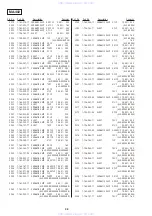
5-5. SERVO/SYSTEM CONTROL, OSD MICROPROCESSOR PIN FUNCTION (MA-402 BOARD IC101)
www . x ia o y u 1 6 3 . c o m
Q Q 3 7 6 3 1 5 1 5 0
9
9
2
8
9
4
2
9
8
T E L 1 3 9 4 2 2 9 6 5 1 3
9
9
2
8
9
4
2
9
8
0
5
1
5
1
3
6
7
3
Q
Q
TEL 13942296513 QQ 376315150 892498299
TEL 13942296513 QQ 376315150 892498299

