


3-4
SEL1224G
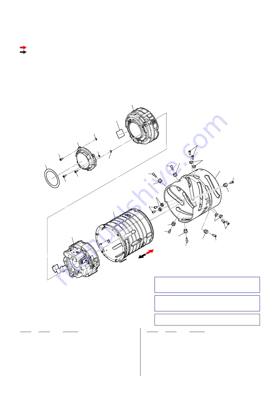
3-4. CAM TUBE SECTION
Red arrow direction
: Shown the front (lens) side
Black arrow direction : Shown the rear (mount) side
151
156
157
158
160
160
160
162
162
162
152
152
153
155
152
154
(Note 1)
154
(Note 1)
154
(Note 1)
159
(Note 2)
159
(Note 2)
159
(Note 2)
161
(Note 2)
158
164
158
161
(Note 2)
163
(Note 2)
163
(Note 2)
163
(Note 2)
161
(Note 2)
165
(Note 3)
(Size 10
u
10 mm)
Note 3:
When replacing Ref. No. 165 cut the new part to the spe-
ci
fi
c size indicated in the
fi
gure before use.
Ref. No.
Part No.
Description
Ref. No.
Part No.
Description
151
4-699-434-01
MASK (PAINTING ), 4 GROUP
152
4-292-406-01 BT2P1.7X4.5B3C
153
4-696-629-01
SERVICE ASSY, G17 FRAME
154
selection parts WASHER, ADJUSTMENT (Note 1)
155
4-696-628-02
SERVICE ASSY, B4 FRAME
156
4-696-627-01
SERVICE ASSY, 2/3 GROUP
157
4-696-630-01 SERVICE
ASSY,
SLIT
TUBE
158
4-696-661-01
SCREW (BT2.0X4.5BNI), PIECE
159
selection parts PIECE, VERTICAL SLIT TUBE (Note 2)
160
4-696-657-01 SCREW
(BT1.7X3.8NI)
161
selection parts PIECE, 2 GROUP (Note 2)
162
4-699-538-01
SCREW (BT1.7X4.2BNI), PIECE
163
selection parts PIECE, 4 GROUP (Note 2)
164
4-696-645-01 TUBE,
CAM
165
2-580-751-01
POLYIMIDE SHEET (Note 3)