1-21
87
Set
ting
s and
Ad
ju
st
m
ent
s
z
Hints
• When recording a digital program with wide signals on
digital broadcasts, refer to the table below.
• This setting is linked with the setting of “TV type” in
the “Easy Setup” display.
When you select “4:3 Letter Box” or “4:3 Pan Scan” of
“TV type” in the “Easy Setup” display, the “Digital
Wide Control” setting is automatically set to “4:3
Letter Box” (page 29).
Caption Service
You can select a service from several closed
caption services for programs that are broadcast
with closed caption.
If the support service number is selected, the
caption appears on the screen.
Note
Digital closed captions cannot be recorded.
Caption Setting
The default setting is decided by the broadcaster.
◆
Character Size
Select a character size from Small, Standard, or
Large.
◆
Character Style
Select a character style from Style 1~7.
◆
Character Color
Change the character color to your preference.
◆
Character Opacity
Change the character opacity.
◆
Edge Color
Change the edge color to your preference.
◆
Edge Type
Change the edge type to your preference.
◆
Background Color
Change the background color to your preference.
◆
Background Opacity
Change the background opacity.
16:9
Record wide signals on digital
broadcasts as they are.
• DVD-RWs/DVD-Rs in VR
mode
• DVD-RWs/DVD-Rs in Video
mode, DVD+RWs/DVD+Rs
(when recording in HQ, HSP,
SP, or LSP mode)
Record as 4:3. When playing a
disc, change the setting on your
TV.
• DVD-RWs/DVD-Rs in Video
mode, DVD+RWs/DVD+Rs
(when recording in ESP, LP, EP,
or SLP mode)
4:3 Letter
Box
Record as 4:3 Letter Box.
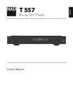
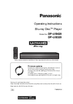
10:10 AM
Options
Setup
Disc Setting
Edit
Title List
Timer
Language
Parental
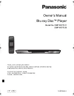
Digital Wide Control
Caption Service
Caption Setting
Front Display
Command Mode
Factory Setting
: 16:9
: Off
: Auto
: DVD 3
DV/D8 Dubbing
Off
Service1
Service2
Service3
Service4
Service5
Service6
,
continued
88
Front Display
Adjusts the lighting of the front panel display.
Command Mode
Changes the command mode of this recorder if
other DVD equipment is assigned the same
command mode. Be sure to match the command
mode of the supplied remote to the setting made
here. For details, see “If you have a Sony DVD
player or more than one Sony DVD recorder” on
page 28.
Factory Setting
Allows you to return the setup settings to their
default settings. Note that all of your previous
settings will be lost.
1
After step 3 on page 84, select “Factory
Setting,” and press ENTER.
2
Select “Start,” and press ENTER.
The setup settings return to their default
settings.
3
Press ENTER when “Finish” appears.
The power automatically turns off and then on
again, and the recorder is reset to the factory
settings.
When the “Easy Setup” display appears,
follow the instructions for Easy Setup
(page 29) from step 5.
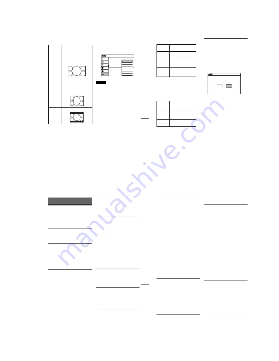
Easy Setup
(Resetting the Recorder)
Select this to run the Easy Setup program.
1
Press SYSTEM MENU while the recorder is
in stop mode.
2
Select “Setup,” and press ENTER.
3
Select “Easy Setup,” and press ENTER.
4
Select “Start,” and press ENTER.
5
Follow the instructions for Easy Setup
(page 29) from step 5.
Auto
Adjusts to low lighting when
power is off.
Bright
Maintains bright lighting
when power is off.
Dimmer
Maintains low lighting
regardless of whether power
is on or off.
Off
Turns off the lighting when
power is off. Maintains the
lighting when power is on.
DVD 1
Select this if the default
command mode conflicts
with other DVD equipment.
DVD 2
Select this if the default
command mode conflicts
with other DVD equipment.
DVD 3
The default command mode
of the recorder.
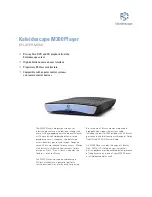
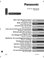
10:10 AM
Easy Setup
Follow the guide to make initial settings.
Before you start,
Check that you have made all necessary connections.
Start
Cancel
89
Ad
di
tio
nal
In
fo
rm
at
io
n
Additional Information
Troubleshooting
If you experience any of the following difficulties
while using the recorder, use this troubleshooting
guide to help remedy the problem before
requesting repairs. Should any problem persist,
consult your nearest Sony dealer.
Power
The power does not turn on.
,
Check that the AC power cord is connected
securely.
Picture
There is no picture.
,
Re-connect all connecting cords securely.
,
The connecting cords are damaged.
,
Check the connection to your TV (page 21).
,
Switch the input selector on your TV (such as to
“VIDEO”) so that the signal from the recorder
appears on the TV screen.
Picture noise appears.
,
Check the connection to your TV (page 17) and
switch the input selector on your TV so that the
signal from the recorder appears on the TV
screen.
,
If the picture output signal from your recorder
passes through your VCR to get to your TV, or if
you are connected to a combination TV/VIDEO
player, the copy-protection signal applied to
some DVD programs could affect picture
quality. If you still experience this problem even
when you connect your recorder directly to your
TV, try connecting your recorder to your TV’s
S VIDEO input.
,
You have set the recorder to progressive format
(the “PROGRESSIVE” indicator lights up) even
though your TV cannot accept the progressive
signal. In this case, set “Progressive” to “Off” in
“Video” setup (page 80).
,
Even if your TV is compatible with progressive
format (480p) signals, the image may be affected
when you set the recorder to progressive format.
In this case, set “Progressive” to “Off” in
“Video” setup (page 80).
There is no picture or the picture noise appears
when connected to the DV IN jack.
,
Try the following:
1
Turn the recorder off and
on again.
2
Turn the connected equipment off
and on again.
3
Disconnect and then connect the
i.LINK cable again.
There is no picture or the picture noise appears
when connected to the HDMI OUT jack.
,
Try the following:
1
Turn the recorder off and
on again.
2
Turn the connected equipment off
and on again.
3
Disconnect and then connect the
HDMI cord again.
,
If the HDMI OUT jack is used for video output,
changing the “HDMI Resolution” setting in the
“Video” setup may solve the problem (page 79).
Connect the TV and the recorder using a video
jack other than the HDMI OUT, and switch the
TV’s input to the connected video input so that
you can see the on-screen displays. Change the
“HDMI Resolution” setting in the “Video” setup,
and switch the TV’s input back to HDMI. If the
picture still does not appear, repeat the steps and
try other options.
,
The recorder is connected to an input device that
is not HDCP compliant (page 22).
TV program reception does not fill the screen.
,
Set the channel manually in “Tuner Preset” setup
(page 76).
,
Select the correct source using the INPUT
button, or select a channel of any TV program
using the CH +/– button.
TV program pictures are distorted.
,
Reorient the TV antenna.
,
Adjust the picture (see the TV’s instruction
manual).
,
Place the recorder and TV farther apart.
,
Place the TV and any bunched antenna cables
farther apart.
TV channels cannot be changed.
,
The channel is disabled (page 77).
,
A timer recording started, which cause the
channels to change.
,
continued
90
The picture from equipment connected to the
recorder’s input jack does not appear on the
screen.
,
If the equipment is connected to the LINE 1 IN
jack, select “LINE1” in the front panel display by
pressing INPUT.
If the equipment is connected to the LINE 2 IN
jacks, select “LINE2” in the front panel display
by pressing INPUT.
The playback picture or TV program from the
equipment connected through the recorder is
distorted.
,
If the playback picture output from a DVD
player, VCR, or tuner goes through your recorder
before reaching your TV, the copy-protection
signal applied to some programs could affect
picture quality. Disconnect the playback
equipment in question and connect it directly to
your TV.
The picture does not fill the screen.
,
Set “TV Type” in “Video” setup to fit the aspect
ratio of your TV (page 79).
The picture does not fill the screen, even
though the aspect ratio is set in “TV Type” in
“Video” setup.
,
The aspect ratio of the disc is fixed on your DVD.
Sound
There is no sound.
,
Re-connect all connections securely.
,
The connecting cord is damaged.
,
The input source setting on the amplifier or the
connection to the amplifier is incorrect.
,
The recorder is in reverse play, fast-forward,
slow motion, or pause mode.
,
If the audio signal does not come through the
DIGITAL AUDIO OUT (OPTICAL or
COAXIAL) jack, check the “Audio” setup
settings (page 81).
No sound is output from the HDMI OUT jack.
,
Try the following:
1
Turn the recorder off and
on again.
2
Turn the connected equipment off
and on again.
3
Disconnect and then connect the
HDMI cord again.
,
The HDMI OUT jack is connected to a DVI
device (DVI jacks do not accept audio signals).
,
The equipment connected to the HDMI OUT
jack does not conform to the audio signal format.
Sound is noisy.
,
When playing a CD with DTS soundtracks, noise
will come from the LINE OUT (AUDIO L/R) or
AUDIO OUT L/R jacks (page 38).
The sound volume is low.
,
The sound volume is low on some DVDs.
The sound volume may improve if you set
“Audio DRC” in “Audio” setup to “Wide
Range” (page 82).
An alternate audio track cannot be recorded or
played.
,
Second Audio Program (SAP) is not available
for all programs. The program you are recording
does not have a second audio program.
,
You have set “Tuner Audio” in “Audio” setup to
“Main” (page 81). Select “SAP” to record
alternate audio programs.
,
If you have connected an AV amplifier to the
DIGITAL AUDIO OUT (OPTICAL or
COAXIAL) jack and want to change the audio
track for a DVD-RW (VR mode)/DVD-R (VR
mode) during playback, set “Dolby Digital” in
“Audio” setup to “D-PCM” (page 81).
,
When recording to a disc other than DVD-RWs
(VR mode)/DVD-Rs (VR mode), set “Line
Audio Input” in “Audio” setup to “Stereo.”
Playback
The disc does not play.
,
The disc is upside down. Insert the disc with the
labeled side facing up.
,
The disc is not correctly inserted.
,
Moisture has condensed inside the recorder.
Remove the disc and leave the recorder turned on
for about half an hour until the moisture
evaporates.
,
If the disc was recorded on another recorder, the
recorder cannot play the disc if it was not
finalized (page 69).
The disc does not start playback from the
beginning.
,
Resume play was activated (page 39).
,
You have inserted a disc whose Title menu or
DVD menu automatically appears on the TV
screen when it is first inserted. Use the menu to
start playback.
Содержание RDR-GX255
Страница 36: ...1 26E MEMO ...
Страница 40: ...2 4E MEMO ...
Страница 42: ...3 4E MEMO ...
Страница 43: ...4 PCB Diagrams 4 2 4 1 4 1 DVD Main PCB 4 3 4 2 Front Main PCB 4 7 4 3 Function Timer PCB 4 11 RDR GXD455 ...
Страница 44: ...4 1 DVD Main PCB 4 4 4 3 COMPONENT SIDE ...
Страница 45: ...4 6 4 5 CONDUCTOR SIDE ...
Страница 46: ...4 8 4 7 4 2 Front Main PCB COMPONENT SIDE ...
Страница 47: ...4 10 4 9 CONDUCTOR SIDE ...
Страница 48: ...4 12E 4 11 4 3 Function Timer PCB COMPONENT SIDE CONDUCTOR SIDE ...
Страница 50: ...5 4 5 3 5 1 S M P S Front Main PCB ...
Страница 51: ...5 6 5 5 5 2 Power Front Main PCB ...
Страница 52: ...5 8 5 7 5 3 Logic Front Main PCB ...
Страница 53: ...5 10 5 9 5 4 Function Jack VCR Front Main PCB ...
Страница 54: ...5 12 5 11 5 5 MPEG Decoder DVD Main PCB ...
Страница 55: ...5 14 5 13 5 6 A V Decoder DVD Main PCB ...
Страница 56: ...5 16 5 15 5 7 In Out DVD Main PCB ...
Страница 57: ...5 18 5 17 5 8 ATSC DVD Main PCB ...
Страница 58: ...5 20 5 19 5 9 Tuner DVD Main PCB ...
Страница 59: ...5 22 5 21 5 10 DV HDMI DVD Main PCB ...
Страница 60: ...5 24E 5 23 5 11 Front Panel Function Timer PCB ...
Страница 77: ...7 1 RDR GXD455 7 REPAIR PARTS LIST 7 1 Exploded Views 7 2 7 2 Electrical Parts List 7 3 ...
Страница 83: ...REVISION HISTORY Ver Date Description of Revision 1 0 2007 06 New RDR GXD455 1 1 2007 07 Supplying IC601 ...