1-12
51
Re
co
rd
in
g
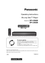
Timer Recording
You can set the timer for a total of 12 programs, up
to one month in advance.
Note that the maximum continuous recording time
for a single title is 12 hours. Contents beyond this
time will not be recorded.
Follow the steps below to set each timer recording
item.
Note
Do not operate your cable box or satellite receiver just
before or during a timer recording. This may prevent the
accurate recording of a program.
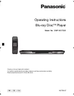
1
Press
Z
OPEN/CLOSE, and place a
recordable disc on the disc tray.
2
Press
Z
OPEN/CLOSE to close the disc
tray.
Wait until “LOAD” disappears from the front
panel display.
Unused discs are automatically formatted. For
the DVD-RW/DVD-R’s recording format
(VR mode or Video mode), see “Formatting a
new disc” on page 48.
3
Press TIMER.
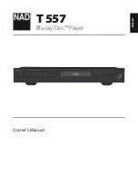
4
Select an item using
<
/
,
and adjust
using
M
/
m
.
A
“Date”: Sets the date using
M
.
To record the same program every day or
the same day every week, press
m
.
The item changes as follows:
Today
y
Sun-Sat (Sunday to Saturday)
y
Mon-Sat (Monday to Saturday)
y
Mon-Fri (Monday to Friday)
y
Sun
(every Sunday)
y
Mon (every Monday)
y
…
y
Sat (every Saturday)
y
1 month later
y
…
y
Today
B
“Start”: Sets the start time.
C
“End”: Sets the stop time.
D
“Ch”: Selects the channel or input
source.
You can switch the broadcast using the
DIGITAL/ANALOG button.
E
“Mode”: Selects the recording mode
(page 47).
To use the Rec Mode Adjust function
(page 52), select “AUTO.”
If you make a mistake, select the item and
change the setting.
+
RW
+
R
-RW
VR
-RW
Video
-R
VR
-R
Video
1
1
2
2
3
3
4
4
5
5
6
6
7
7
8
8
0
0
9
9
M
/
m
/
<
/
,
,
ENTER
Z
OPEN/
CLOSE
x
STOP
SYSTEM
MENU
TIMER
DIGITAL/
ANALOG
DV IN
L(MONO) AU
DIO R
VIDEO
S VIDEO
LINE-2 IN
ONE-TOUCH D
UBBING
Recording side facing down
01
DVD
04/15
09:00PM
10:00PM
CH8
---
--/--
--:--
--:--
----
---
04
---
--/--
--:--
--:--
----
---
05
---
--/--
--:--
--:--
----
---
06
03
---
--/--
--:--
--:--
----
---
02
DVD
04/30
09:15PM
09:45PM
CH11
10:10 AM
No Rec To
Date
Start
End
Source Mode Edit
Timer – Standard
No.01
:
PM
PM
:
09
00
10
00
Ch 8
SP
1
2
3
4
5
Date
Start
End
Ch
Mode
Today
,
continued
52
5
Press ENTER.
The Timer List menu (page 54) appears.
The
c
indicator lights up in the front panel
display, and the recorder is ready to start
recording.
• If the
c
indicator flashes in the front panel
display, a recordable disc is not inserted.
Insert a recordable disc and check that there
is enough disc space for the recording.
• If timer settings overlap, a message appears.
To change or cancel a timer recording, select
“Edit” from the Timer List (page 54).
6
Press SYSTEM MENU to turn off the menu.
There is no need to turn off the recorder before
the timer recording starts.
To stop recording
Press
x
STOP twice.
Note that it may take a few seconds for the
recorder to stop recording.
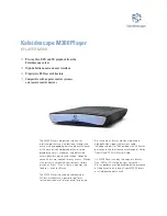
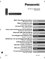
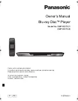
If timer settings overlap
The program that starts first has priority and the
second program starts recording only after the first
program has finished. If the programs start at the
same time, the program listed first in the menu has
priority. If the end time of one setting and the start
time of another timer setting is the same, the
beginning of the program that starts later will be
cut.
To change or cancel timer recording
See “Changing or Canceling Timer Settings
(Timer List)” on page 54.
To use the Rec Mode Adjust function
If the remaining disc space is not enough for the
current recording, the recorder automatically
adjusts the recording mode. Select “AUTO” for
“Mode” when setting the timer.
z
Hints
• You can play the recorded program by selecting the
program title in the Title List menu.
• You can also turn on the timer programming menu
from the System Menu. Press SYSTEM MENU to
select “Timer,” and select “Timer-Standard.”
• You can use the number buttons and the dot (·) button
to select a channel.
• You can select a video source from the LINE 1 IN or
LINE 2 IN jacks, using the INPUT button.
Notes
• To record a cable or satellite program, turn on the cable
box or satellite receiver and select the program you
want to record. Leave the cable box or satellite receiver
turned on until the recorder finishes recording.
• Even when correctly set, the program may not be
recorded if another recording is underway, or other
prioritized timer setting overlaps.
• Before the timer recording starts, “TIMER REC”
flashes in the front panel display.
• The recorder automatically turns off when a timer
recording finishes, even if the recording started with
the recorder turned on.
• The recorder does not record programs with Copy-
Never signals. Such recordings stop after a few
seconds.
• Digital closed captions cannot be recorded (page 35).
• For audio settings, “Stream 1” is usually recorded
(page 35).
• When you set the Digital Rating, a program with a
digital rating beyond your limit setting cannot be
recorded correctly (page 85).
7:00
8:00
9:00
10:00
7:00
8:00
9:00
10:00
Program 1
Program 2
will be cut off
Program 1
Program 2
will be cut off
53
Re
co
rd
in
g
Recording From Connected
Equipment With a Timer
(Synchro Rec)
You can set the recorder to automatically record
programs from connected equipment that has a
timer function (such as a satellite tuner). Connect
the equipment to the LINE 1 IN jacks on the rear
of the recorder (page 18).
When the connected equipment turns on, the
recorder starts recording a program from the LINE
1 IN jacks.
1
Insert a recordable disc.
2
Select the line input audio.
Set “Line Audio Input” of “Audio” setup to
“Stereo” or “Main/Sub” in the “Setup”
display (page 83).
3
Press REC MODE repeatedly to select the
recording mode.
The display changes on the TV screen as
follows:
For details about the recording mode, see
page 47.
4
Set the timer on the connected equipment
to the time you want to record, and turn it
off.
5
Press SYNCHRO REC.
The SYNCHRO REC indicator lights up on
the front panel and the recorder stands by for
Synchro-Rec.
The recorder starts recording when a signal is
received from the connected equipment.
When the connected equipment turns off, the
recording stops and the recorder turns off.
To stop recording
Press
x
STOP twice.
To cancel a Synchro-Rec function
Press SYNCHRO REC before recording starts.
The SYNCHRO REC indicator on the recorder
turns off.
If you press SYNCHRO REC during Synchro-
Rec, the recording stops, the SYNCHRO REC
indicator turns off, and the recorder turns off.
+
RW
+
R
-RW
VR
-RW
Video
-R
VR
-R
Video
1
1
2
2
3
3
4
4
5
5
6
6
7
7
8
8
0
0
9
9
M
/
m
/
<
/
,
,
ENTER
SYNCHRO
REC
x
STOP
REC MODE
SYSTEM
MENU
HQ
SP
HSP
LSP
SLP
LP
EP
ESP
,
continued
54
If the timer settings of a Synchro-Recording
and another timer recording overlap
Regardless of whether or not the program is a
Synchro-Rec program, the program that starts first
has priority. The recorder starts recording the
second program about ten seconds after the first
program has finished. If the end time of one
setting and the start time of another timer setting is
the same, the beginning of the program that starts
later will be cut.
Notes
• The recorder starts recording only after detecting the
video signal from the connected equipment. The
beginning of the program may not be recorded
regardless of whether or not the recorder’s power is on
or off.
• To use the connected equipment during Synchro-Rec
standby, cancel the standby mode by pressing
SYNCHRO REC. To return to standby mode again, be
sure to turn off the equipment and press SYNCHRO
REC, before Synchro-Rec starts.
• The Synchro-Rec function does not work with some
tuners. For details, see the tuner’s operating
instructions.
• During Synchro-Rec standby, the Auto Clock Set
function does not work (page 78).
• After a recording has finished, the recorder enters the
Synchro-Rec standby mode until the SYNCHRO REC
indicator turns off.
• If Synchro-Rec starts with the recorder turned on, the
recorder will turn off when the recording ends.
• The recorder does not record programs with Copy-
Never signals. Such recordings stop after a few
seconds.
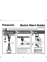
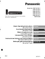
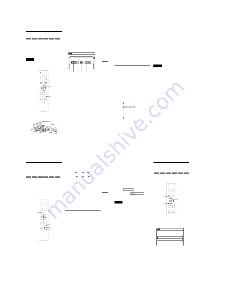
Changing or Canceling
Timer Settings (Timer List)
You can change or cancel timer settings using the
Timer List menu.
1
Press SYSTEM MENU.
The System Menu appears.
2
Select “Timer,” and press ENTER.
3
Select “Timer List,” and press ENTER.
Timer information displays the recording
date, time, recording mode, etc.
If there are more than six timer settings, press
m
to display the next page.
4
Select the timer setting you want to change
or cancel, and press ENTER.
The sub-menu appears.
7:00
8:00
9:00
10:00
Program 1
Program 2
will be cut off
+
RW
+
R
-RW
VR
-RW
Video
-R
VR
-R
Video
1
1
2
2
3
3
4
4
5
5
6
6
7
7
8
8
0
0
9
9
SYSTEM
MENU
M
/
m
/
<
/
,
,
ENTER
O
RETURN
01
04/15
09:00PM
10:00PM
Ch 8
--/--
--:--
--:--
----
---
04
--/--
--:--
--:--
----
---
05
--/--
--:--
--:--
----
---
06
03
--/--
--:--
--:--
----
---
02
04/30
09:15PM
09:45PM
D11.1
10:10 AM
SP
SP
Timer List
No
Date
Start
End
Ch
Mode Edit
Содержание RDR-GX255
Страница 36: ...1 26E MEMO ...
Страница 40: ...2 4E MEMO ...
Страница 42: ...3 4E MEMO ...
Страница 43: ...4 PCB Diagrams 4 2 4 1 4 1 DVD Main PCB 4 3 4 2 Front Main PCB 4 7 4 3 Function Timer PCB 4 11 RDR GXD455 ...
Страница 44: ...4 1 DVD Main PCB 4 4 4 3 COMPONENT SIDE ...
Страница 45: ...4 6 4 5 CONDUCTOR SIDE ...
Страница 46: ...4 8 4 7 4 2 Front Main PCB COMPONENT SIDE ...
Страница 47: ...4 10 4 9 CONDUCTOR SIDE ...
Страница 48: ...4 12E 4 11 4 3 Function Timer PCB COMPONENT SIDE CONDUCTOR SIDE ...
Страница 50: ...5 4 5 3 5 1 S M P S Front Main PCB ...
Страница 51: ...5 6 5 5 5 2 Power Front Main PCB ...
Страница 52: ...5 8 5 7 5 3 Logic Front Main PCB ...
Страница 53: ...5 10 5 9 5 4 Function Jack VCR Front Main PCB ...
Страница 54: ...5 12 5 11 5 5 MPEG Decoder DVD Main PCB ...
Страница 55: ...5 14 5 13 5 6 A V Decoder DVD Main PCB ...
Страница 56: ...5 16 5 15 5 7 In Out DVD Main PCB ...
Страница 57: ...5 18 5 17 5 8 ATSC DVD Main PCB ...
Страница 58: ...5 20 5 19 5 9 Tuner DVD Main PCB ...
Страница 59: ...5 22 5 21 5 10 DV HDMI DVD Main PCB ...
Страница 60: ...5 24E 5 23 5 11 Front Panel Function Timer PCB ...
Страница 77: ...7 1 RDR GXD455 7 REPAIR PARTS LIST 7 1 Exploded Views 7 2 7 2 Electrical Parts List 7 3 ...
Страница 83: ...REVISION HISTORY Ver Date Description of Revision 1 0 2007 06 New RDR GXD455 1 1 2007 07 Supplying IC601 ...