1-4
19
Ho
ok
u
p
s an
d Sett
ings
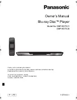
B: Cable box with an antenna output only
With this hookup, you can record any channel on the satellite receiver or cable box. Be sure that the cable
box or satellite receiver is turned on.
To record cable programs, you need to match the channel on the recorder (2ch, 3ch or 4ch) to the antenna
output channel on the cable box (2ch, 3ch or 4ch).
L
R
VIDEO
AUDIO
LINE OUT
VHF/UHF
VIDEO
Y
L
PB
R
PR
AUDIO
LINE 1 IN
AUDIO OUT
S VIDEO OUT
COMPONENT
VIDEO OUT
DIGITAL AUDIO OUT
OPTICAL COAXIAL
HDMI OUT
IN
OUT
VHF/UHF
IN
OUT
ANT IN
TO TV
Antenna cable
(supplied)
Cable box
DVD recorder
to VHF/UHF IN
to VHF/UHF
OUT
to antenna input
: Signal flow
TV
Wall
,
continued
20
C: Cable without cable box, or antenna only (no cable TV)
Use this hookup if you watch cable channels without a cable box. Also use this hookup if you are using
a VHF/UHF antenna or separate VHF and UHF antennas.
With this hookup, you can record any channel by selecting the channel on the recorder.
L
R
VIDEO
AUDIO
LINE OUT
VHF/UHF
VIDEO
Y
L
PB
R
PR
AUDIO
LINE 1 IN
AUDIO OUT
S VIDEO OUT
COMPONENT
VIDEO OUT
DIGITAL AUDIO OUT
OPTICAL COAXIAL
HDMI OUT
IN
OUT
VHF/UHF
IN
OUT
to VHF/UHF
OUT
to antenna input
: Signal flow
DVD recorder
to VHF/UHF IN
Antenna cable
(supplied)
TV
Wall
21
Ho
ok
u
p
s an
d Sett
ings
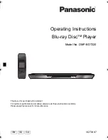
Step 3: Connecting to Your TV
Connect the supplied audio/video cord to the LINE OUT (VIDEO/AUDIO L/R) jacks of the recorder.
To enjoy higher quality images, connect an S video cord (not supplied) instead of the yellow (video) plug.
When using this connection, be sure to connect the audio cord to the LINE OUT (AUDIO L/R) jacks.
When playing “wide screen” images
Some recorded images may not fit your TV screen. To change the picture size, see page 79.
Notes
• Do not connect to the S VIDEO OUT and yellow LINE OUT (VIDEO) jacks at the same time.
• Do not connect your TV’s audio output jacks to the LINE IN (AUDIO L/R) jacks at the same time. This will cause
unwanted noise to come from your TV’s speakers.
L
R
VIDEO
AUDIO
LINE OUT
VHF/UHF
VIDEO
Y
L
PB
R
PR
AUDIO
LINE 1 IN
AUDIO OUT
S VIDEO OUT
COMPONENT
VIDEO OUT
DIGITAL AUDIO OUT
OPTICAL COAXIAL
HDMI OUT
IN
OUT
L
R
VIDEO
AUDIO
LINE OUT
VIDEO
AUDIO
LINE 1 IN
S VIDEO OUT
AUDIO
INPUT
R
L
VIDEO
INPUT
S VIDEO
: Signal flow
S video cord
(not supplied)
TV or projector
(red)
(white) (yellow)
Audio/video cord
(supplied)
(red)
(white)
(yellow)
to S VIDEO OUT
DVD recorder
to LINE OUT
(VIDEO/AUDIO L/R)
,
continued
22
If your TV has an HDMI input jack
Connect the HDMI* OUT jack using a certified HDMI cord (not supplied). You will enjoy high-quality
picture and sound. The HDMI indicator lights up on the front panel when the recorder outputs signals
through the HDMI OUT jack.
Be sure to turn off the recorder before connecting an HDMI cord.
* This DVD recorder incorporates High-Definition Multimedia Interface (HDMI
TM
) technology.
HDMI, the HDMI logo and High-Definition Multimedia Interface are trademarks or registered trademarks of HDMI
Licensing LLC.
Notes
• You cannot connect the HDMI OUT jack to DVI jacks that are not HDCP compliant (e.g., DVI jacks on PC displays).
• HD (High Definition) signal through this recorder is converted to SD (Standard Definition) signal, even if the HDMI
OUT connection is used.
L
R
VIDEO
AUDIO
LINE OUT
VHF/UHF
VIDEO
Y
L
PB
R
PR
AUDIO
LINE 1 IN
AUDIO OUT
S VIDEO OUT
COMPONENT
VIDEO OUT
DIGITAL AUDIO OUT
OPTICAL COAXIAL
HDMI OUT
IN
OUT
HDMI IN
HDMI OUT
: Signal flow
TV or
projector
to HDMI OUT
DVD recorder
HDMI cord (not supplied)
to HDMI input
Содержание RDR-GX255
Страница 36: ...1 26E MEMO ...
Страница 40: ...2 4E MEMO ...
Страница 42: ...3 4E MEMO ...
Страница 43: ...4 PCB Diagrams 4 2 4 1 4 1 DVD Main PCB 4 3 4 2 Front Main PCB 4 7 4 3 Function Timer PCB 4 11 RDR GXD455 ...
Страница 44: ...4 1 DVD Main PCB 4 4 4 3 COMPONENT SIDE ...
Страница 45: ...4 6 4 5 CONDUCTOR SIDE ...
Страница 46: ...4 8 4 7 4 2 Front Main PCB COMPONENT SIDE ...
Страница 47: ...4 10 4 9 CONDUCTOR SIDE ...
Страница 48: ...4 12E 4 11 4 3 Function Timer PCB COMPONENT SIDE CONDUCTOR SIDE ...
Страница 50: ...5 4 5 3 5 1 S M P S Front Main PCB ...
Страница 51: ...5 6 5 5 5 2 Power Front Main PCB ...
Страница 52: ...5 8 5 7 5 3 Logic Front Main PCB ...
Страница 53: ...5 10 5 9 5 4 Function Jack VCR Front Main PCB ...
Страница 54: ...5 12 5 11 5 5 MPEG Decoder DVD Main PCB ...
Страница 55: ...5 14 5 13 5 6 A V Decoder DVD Main PCB ...
Страница 56: ...5 16 5 15 5 7 In Out DVD Main PCB ...
Страница 57: ...5 18 5 17 5 8 ATSC DVD Main PCB ...
Страница 58: ...5 20 5 19 5 9 Tuner DVD Main PCB ...
Страница 59: ...5 22 5 21 5 10 DV HDMI DVD Main PCB ...
Страница 60: ...5 24E 5 23 5 11 Front Panel Function Timer PCB ...
Страница 77: ...7 1 RDR GXD455 7 REPAIR PARTS LIST 7 1 Exploded Views 7 2 7 2 Electrical Parts List 7 3 ...
Страница 83: ...REVISION HISTORY Ver Date Description of Revision 1 0 2007 06 New RDR GXD455 1 1 2007 07 Supplying IC601 ...