PS-HX500
PS-HX500
15
15
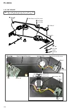
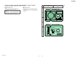
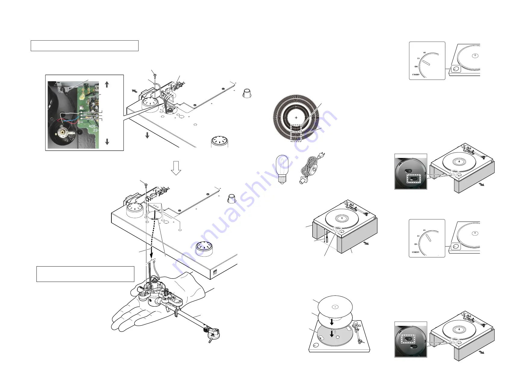
2-11. TONE ARM ASSY
[white]
[red]
wire
MAIN board
[blue/green]
:LUHVHWWLQJ
2
screw
(3
u
12)
1
Remove the
three
solders.
3
wire
rear side
hole
5
Draw the wire out
of the hole.
6
tone arm assy
front side
rear side
top side
4
six screws
(PTP3
u
14)
Note
3:
When removing the screws, make sure
that you hold the tone arm assy.
Note 2:
If you remove the six screws (step 4), the tone arm assy
will fall. When removing the screws, make sure that
you hold the tone arm assy.
Note 1:
When turning the main unit over, refer to “NOTE IN THE
CASE OF THE REVERSING THE MAIN UNIT” on page 3.
SECTION 3
ELECTRICAL ADJUSTMENT
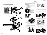
DC MOTOR SPEED ADJUSTMENT
When replace the motor, perform the DC motor speed adjustment.
Necessary equipment:
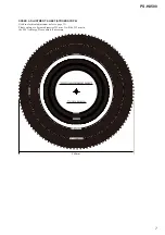
• Speed adjustment sheet (stroboscope) (Fig A)
Note:
Enlarge “SPEED ADJUSTMENT SHEET (STROBOSCOPE)”
of page 7 and print it.
• LED light bulb without the inverter (Fig. B)
• LED light bulb socket (Fig. C)
• Insulation
fl
athead screwdriver for resistor adjustment
• Stand for putting the main unit
Power supply frequency
for 50 Hz.
inside : for 45 rpm check
outside : for 33 rpm check
Power supply frequency
for 60 Hz.
inside : for 45 rpm check
outside : for 33 rpm check
– Fig. A –
– Fig. B –
– Fig. C –
Installation method:
Holes for adjustment
(Not covered the holes by a stand)
front side
Height that the flathead
screwdriver can be used.
Stand
Stand
Procedure:
1. Installing the main unit by referring to “Installation method”.
2. Place the rubber mat onto the turntable, and place the speed
adjustment sheet (stroboscope) onto it.
Rubber mat
Turntable
Speed adjustment
sheet
3. The turntable is rotated at a rotation speed 33 rpm.
SPEED/POWER
rotary switch knob
4. Connect the socket
fi
tted with a LED light bulb into an electri-
cal outlet.
5. The LED light bulb is lit near to the turntable.
6. Insert the insulation
fl
athead screwdriver for resistor adjust-
ment into screw hole “33” at the bottom of the main unit.
Adjust the turntable speed by rotating the insulation
fl
athead
screwdriver to the left or right so that the speed adjustment
sheet pattern looks like it has stopped moving.
Note 1:
Check the applicable place of the speed adjustment sheet to match
the power supply frequency (50 Hz/60 Hz) that is used in the LED
light bulb.
front side
– Bottom view –
7. When you have completed the adjustment of 33 rpm, then per-
form the adjustment of 45 rpm.
8. The turntable is rotated at a rotation speed 45 rpm.
SPEED/POWER
rotary switch knob
9. The LED light bulb is lit near to the turntable.
10. Insert the insulation
fl
athead screwdriver for resistor adjust-
ment into screw hole “45” at the bottom of the main unit.
Adjust the turntable speed by rotating the insulation
fl
athead
screwdriver to the left or right so that the speed adjustment
sheet pattern looks like it has stopped moving.
Note 2:
Check the applicable place of the speed adjustment sheet to match
the power supply frequency (50 Hz/60 Hz) that is used in the LED
light bulb.
front side
– Bottom view –
Содержание PS-HX500
Страница 6: ...MEMO PS HX500 6 ...
Страница 8: ...MEMO PS HX500 8 ...
Страница 16: ...PS HX500 PS HX500 16 16 SECTION 4 DIAGRAMS 4 1 BLOCK DIAGRAM ORFN ...
Страница 26: ...PS HX500 REVISION HISTORY Ver Date Description of Revision 1 0 2016 03 New ...


