PS-HX500
12
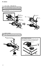
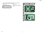
2-7. FOOT ASSY, COVER_MOTOR
2-8. SWITCH KNOB
foot assy (rubber block)
1
Rotate the foot assy (rubber block)
in the direction of the arrow.
front side
bottom side
5
screw
(3
u
12)
2
foot assy
(rubber
block)
4
foot assy
(base
block)
3
screw
(3
u
12)
5
three screws
(3
u
12)
6
cover_motor
hole
1
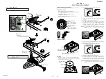
Push the switch knob by
a flathead screwdriver.
How to install the switch knob
When installing the switch knob to the rotary encoder, align
the directions of the D-shaped tip of the rotary encoder and
the D-shaped notch at the inner side of the switch knob.
rotary encoder
2
switch knob
switch knob
front side
bottom side
front side
top side
Note 1:
When turning the main unit over, refer to “NOTE IN THE
CASE OF THE REVERSING THE MAIN UNIT” on page 3.
Note:
When turning the main unit over, refer to “NOTE IN THE
CASE OF THE REVERSING THE MAIN UNIT” on page 3.
Note 2:
All four foot assys ( base) can be removed using the
same procedure.
Содержание PS-HX500
Страница 6: ...MEMO PS HX500 6 ...
Страница 8: ...MEMO PS HX500 8 ...
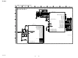
Страница 16: ...PS HX500 PS HX500 16 16 SECTION 4 DIAGRAMS 4 1 BLOCK DIAGRAM ORFN ...
Страница 26: ...PS HX500 REVISION HISTORY Ver Date Description of Revision 1 0 2016 03 New ...


