


PS-HX500
13
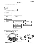
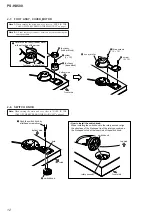
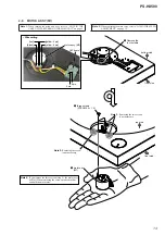
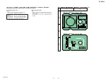
2-9. MOTOR ASSY (M1)
front side
bottom side
2
three screws
(STEP
M2.5
u
1.5)
3
motor assy
(M1)
1
Remove the
four
solders.
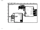
:LUHVHWWLQJ
SW board
motor assy (M1)
[yellow: 5 pin]
6 pin
[yellow: 6 pin]
[red]
[black]
5 pin
front side
top side
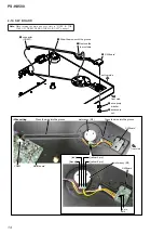
Note 3:
Removing the two screws
is not necessary.
Note 3:
Removing the screw
is not necessary.
Note 4:
If you remove the three screws (step 2), the motor assy
will fall. When removing the screws, make sure that
you hold the motor assy.
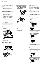
Note 1:
When turning the main unit over, refer to “NOTE IN THE
CASE OF THE REVERSING THE MAIN UNIT” on page 3.
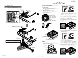
Note 2:
When replacing the motor assy, refer to “DC MOTOR SPEED
ADJUSTMENT” on page 15.
Содержание PS-HX500
Страница 6: ...MEMO PS HX500 6 ...
Страница 8: ...MEMO PS HX500 8 ...
Страница 16: ...PS HX500 PS HX500 16 16 SECTION 4 DIAGRAMS 4 1 BLOCK DIAGRAM ORFN ...
Страница 26: ...PS HX500 REVISION HISTORY Ver Date Description of Revision 1 0 2016 03 New ...