51
Name and Function of Parts
2. Disconnect the ODA control cable.
If the ODA control cable is disconnected first, the drive
unit may turn off and then on again.
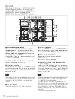
g
Drive unit mount slots
Allow you to install up to four optional drive units
(ODS-D77F/D280F).
h
CARTRIDGE IN indicator
Lit green when the drive unit is turned on and a cartridge
is inserted in the drive unit.
i
DC IN connector
Connect to the DC OUT connector of a power supply unit
to supply power to the drive unit.
When connecting the drive DC cable while the library
power supply is turned on, use the following procedure.
1. Connect the ODA control cable.
2. Connect the drive DC cable to the DC IN connector.
If the drive DC cable is connected first, the drive unit may
enter “Miscommunication” state, requiring the drive unit
to be restarted using the Library Maintenance Web UI.
Similarly, when removing a drive unit, use the following
procedure.
1. Disconnect the drive DC cable.
2. Disconnect the ODA control cable.
If the ODA control cable is disconnected first, the drive
unit may turn off and then on again.
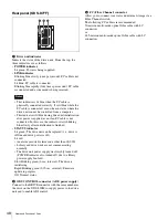
j
FC (Fibre Channel) connectors
Allow you to connect to servers and external storage via a
Fibre Channel switch.
k
ODS CONTROL connector (ADI)
Connect to the DRIVE connector with the same number as
the drive on the ODS-L60E to enable ADI control.
l
Drive unit indicators
Indicate the status of the drive units. From the top, the
three indicators are as follows.
•
POWER indicator
Lit green: Power is being supplied.
•
LINK indicator
Blinking blue slowly (once per second): FC cable is not
connected.
Lit blue: FC cable is connected.
Blinking blue rapidly (four times per second): FC cable
is connected and a command is being received.
• This indicator is lit blue when the FC cable is
physically connected correctly. It is lit blue while the
FC cable is connected, even when in states where the
drive unit cannot be controlled from a computer.
• This indicator is lit blue during drive unit initialization
after power is applied, even if an FC cable is not
connected. In this case, the indicator starts blinking
blue slowly after initialization is finished.
•
STATUS indicator
Lit green: The drive unit can be replaced (i.e., drive is
offline and drive power is off).
Lit red:
• An alarm occurred (alarm code other than 00-000).
• Library and drive units are not communicating
normally.
• The drive unit power supply was forcibly turned off
(POWER indicator also turned off) due to a library
power supply fan fault.
Slow blinking green (1-sec. interval): The drive is
initializing.
Rapid blinking green (0.25-sec. interval): Firmware
update in progress.
Off: Normal status.
m
OUT 1 (unit interconnection) connector
Connect to the IN 1 connector of the master unit
(ODS-L30M) or another extension unit (ODS-L60E/
L100E) using unit interconnection cable 1 (supplied with
the extension unit).
n
OUT 2 (unit interconnection) connector
Connect to the IN 2 connector of the master unit
(ODS-L30M) or another extension unit (ODS-L60E/
L100E) using unit interconnection cable 2 (supplied with
the extension unit).
o
IN 2 (unit interconnection) connector
Connect to the OUT 2 connector of the master unit
(ODS-L30M) or another extension unit (ODS-L60E/
L100E) using unit interconnection cable 2 (supplied with
the extension unit).
p
IN 1 (unit interconnection) connector
Connect to the OUT 1 connector of the master unit
(ODS-L30M) or another extension unit (ODS-L60E/
L100E) using unit interconnection cable 1 (supplied with
the extension unit).
Note
Notes

