


Location and Function of Parts and Controls
9
Location and Function of Parts and Controls
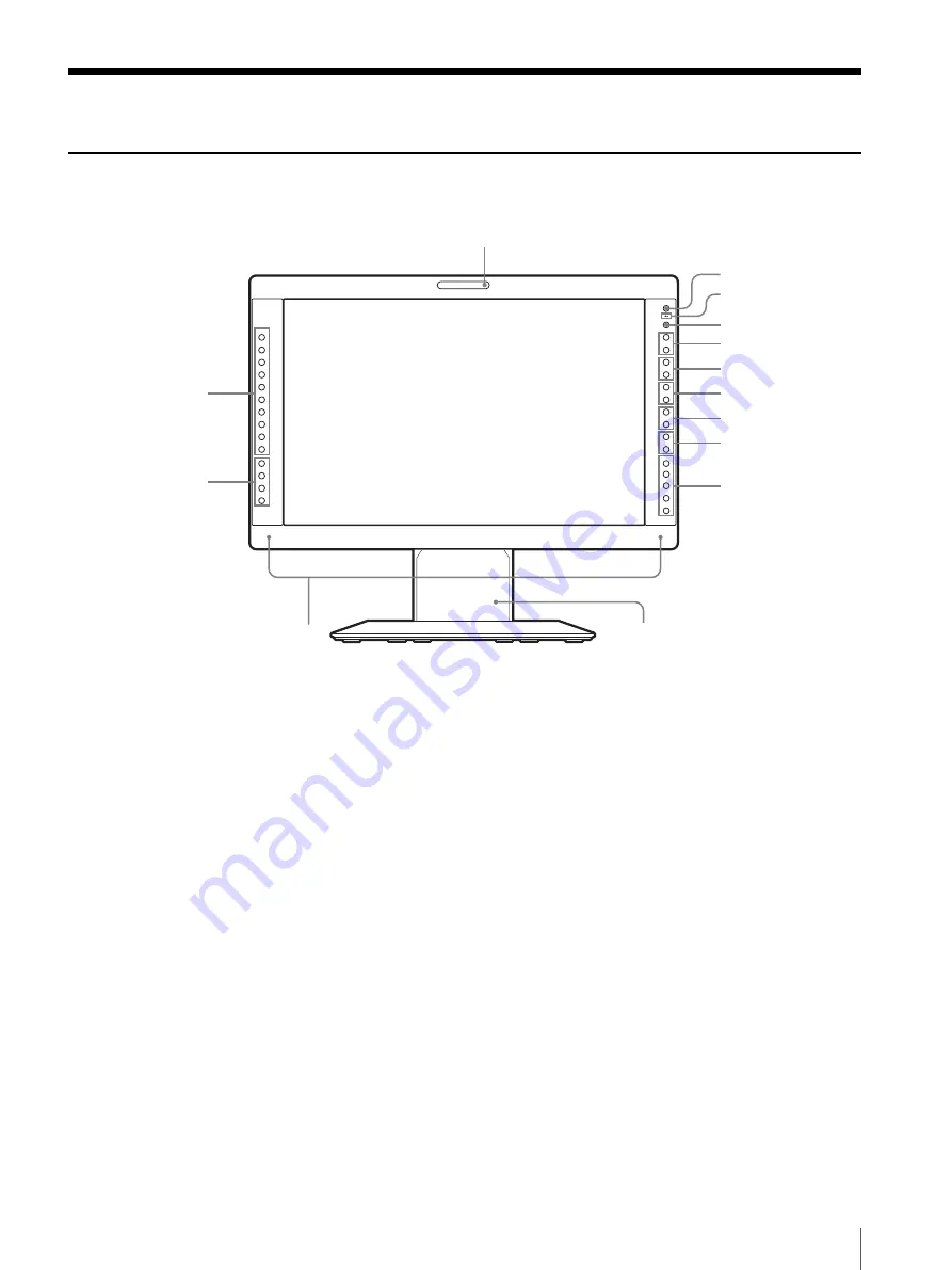
Front Panel
a
Tally lamp
You can check the status of the monitor by the color of
the tally lamp.
The tally lamp lights in red, green or amber according to
the setting of PARALLEL REMOTE in the REMOTE
menu.
b
1
(standby) switch and indicator
When you press the switch to turn on the power in
standby mode (the power switch on the rear panel is
turned on), the indicator lights in green.
When you press this switch again, the monitor is set in
standby mode and the indicator lights in red.
c
-
(key inhibit) indicator
Lights in red when the key inhibit is set to ON.
d
CONTROL button
Press to display the buttons on the front panel. Press
again to clear the display.
e
VOLUME buttons
Press the + button to increase the volume or the – button
to decrease it.
f
CONTRAST buttons
Adjusts the picture contrast.
Press the + button to make the contrast higher or the –
button to make it lower.
g
PHASE buttons
Adjusts color tones.
Press the + button to make the skin tones greenish or the
– button to make them purplish.
h
CHROMA buttons
Adjusts the color intensity.
Press the + button to increase the color intensity or the –
button to decrease it.
i
BRIGHT (brightness) buttons
Adjusts the picture brightness.
Press the + button to increase the brightness or the –
button to decrease it.
j
Menu operation buttons
Displays or sets the on-screen menu.
MENU button
Press to display the on-screen menu.
Press again to clear the menu.
COMPOSITE
COMPONENT
Y/C
RGB
A-1
A-2
B-1
B-2
DVI
F1
F2
F3
F4
HD15
–
+
–
+
–
+
–
+
–
+
–
+
5
qa
qs
qf
4
6
7
8
9
0
3
2
1
qd
Содержание LMD1751WCC
Страница 41: ...Sony Corporation ...


