41
Audio with K Board
Overview
This section discusses the second type of audio circuit that uses the K
board. The K board allows for up to six different audio source inputs. It
also contains ICs that perform all necessary audio processing, including
volume control and SRS. SRS is not contained in all models that use the
K board. We will also discuss the second type of Audio Amp.
Audio Inputs and Processing
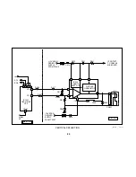
Larger BA-5 chassis sets can have up to six audio inputs, Video 1 through
4 and inputs for two tuners. No matter what source is chosen, both chan-
nels of audio are applied to the K board via CN460 and CN450. Then
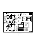
both channels of all sources are applied to IC404 Audio Processor.
IC404 Audio Processor contains a switching network that will switch the
selected source to the various outputs. The selection is performed via I²C
commands from the Syscon. The audio selected is directly output from
IC404/11 and 30 Monitor Out. This signal will be sent to J204 Monitor Out
jack on the A board.
The signals will also be applied to the following internal circuits: AGC,
BBE, volume, matrix surround sound, tone and another volume circuit.
Data from the I²C bus will determine how much audio processing is per-
formed. The left and right signals are output for the Var/Fix Output at
J402 on the A board from IC404/ 12 and 29. The customer can select
from the menu if they want this output to be fixed or variable.
The outputs from IC404/13 and 28 are the main audio outputs of the set.
Depending on the model, this audio will be input to IC403 SRS or to the A
board for amplification. If the model contains SRS, these signals are
input at IC403/23 and 24. The audio is processed by the SRS circuit
using the two control outputs from IC404/22 and 23. These control out-
puts are used because IC403 SRS is not I²C compatible. IC403 then
outputs audio from pins 15 and 16.
Whether the unit contains the SRS IC or not, audio will eventually be
applied to CN450/5 and 6. From there it will go to the A board via CN460/
5 and 6.
Audio Amp
Once the audio is on the A board, it is applied to the same RC network
used on models without K boards. The values of the resistors in this case
will determine if the set will output 10x2 watts per channel or 15x2 watts
per channel. The signals are applied to IC402 using two pins for each
channel. The output is differential and follows the same path as models
without K boards. Some larger sets do not contain headphone jacks. If
the set does not, audio is applied to the speakers from the + outputs of
IC402. The – outputs of IC402 are applied to the – side of the speakers.
Содержание FD TRINITRON WEGA KV-13FM12
Страница 27: ...22 NOTES ...
Страница 48: ...APPENDIX ...

