7
Power Supply and Self-Diagnostics
Power Supply
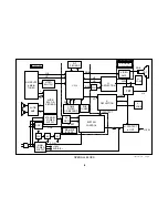
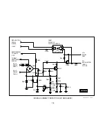
When the unit is first plugged in, power is applied through the AC In block
to the Standby Supply. The Standby Supply powers the System Control
IC, EEPROM, remote sensor and reset circuits. If a Power ON command
is received after reset, the System Control IC outputs voltages to turn ON
the Power and Degauss relays. When operating correctly, the following
can be observed in sequence:
•
The power relay clicks;
•
One second later the degauss relay clicks and the hum of the DGC is
heard for about two seconds; and
•
The degauss relay clicks again two seconds later and then a picture is
displayed.
This entire sequence occurs in the first 5-10 seconds the unit is powered
ON. During this time, the Standby/Timer LED will be flashing approxi-
mately once per second.
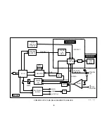
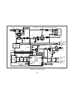
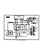
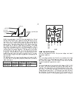
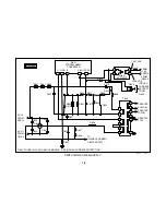
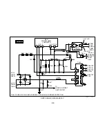
The main power supply in the BA-5 chassis uses one switching IC to
control switching of the B+ through a transformer. The transformer pri-
mary couples the signal to the secondary. The secondary signals are
used to create three DC voltages, which are used to supply power to the
rest of the set. Feedback from the primary side of the transformer and the
+135 volt line created by the secondary are used to control the switching
frequency. The IC also has three built-in protection circuits. They are for
over voltage, over current and thermal protection. These protection cir-
cuits will be covered in the Switching Power Supply section.
Protection
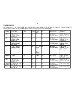
Protection circuits are included to deactivate the set if the following fail-
ures occur:
S7.5 volt OVP
– If over voltage occurs on this line, a LOW will
be output to the base of the relay drive transistor. This shuts the set OFF.
+135 volt OCP
– This sensor monitors the voltage across a resistor that
feeds the H Out and FBT and protects a135 volt OCP. When
OCP is detected, the protect latch is activated. When the latch is acti-
vated, drive to the relay is stopped. This shuts down the main power
supply. A signal is also sent to the Syscon IC to be used by the Self-
Diagnostics.
H Protect
– Or hold down is used to keep the picture tube from emitting
harmful x-rays if a failure should occur that causes the High Voltage to
rise. When this circuit is activated, it also turns the latch ON. This turns
drive to the power relay OFF and sends a signal to the Syscon to be used
for self-diagnostics.
AKB Protect
– Or IK protect causes the video to be blanked if the YCJ
does not receive the correct feedback from the IK line. The IK line’s
voltage is representative of the amount of current being drawn by the
tube. This current is monitored during vertical blanking. The YCJ outputs
one H line for each color and monitors the returning IK voltage. If this
voltage is not within the correct operating window, the YCJ alerts the
Syscon IC via the I²C bus for use by the Self-Diagnostics.
I Protect
- I protect occurs when the Vertical Output IC does not return
samples of its pump-up pulse to the Syscon. When these pulses are
missing, it is an indicator that the vertical section is not working. The
Syscon IC monitors these pulses for Self-Diagnostics and protection pur-
poses. When the pulses are missing, the main power supply is turned
OFF and Self-Diagnostics are activated.
Содержание FD TRINITRON WEGA KV-13FM12
Страница 27: ...22 NOTES ...
Страница 48: ...APPENDIX ...


