13
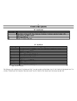
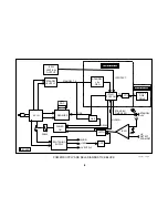
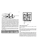
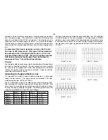
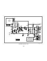
R621
Q601/B
D606/G
80 volts
20 volts
.6 volts
14 volts
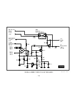
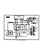
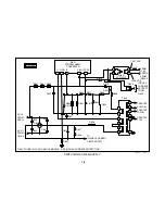
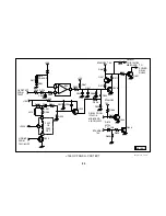
Inrush Timing Diagram
Inrush Current Protection
Overview
Sets with 20-inch tubes and below use R605 and R606 (shown in the
Power ON/Degaussing section) for inrush current protection. Since more
current is drawn when a set with a bigger CRT is turned ON, an alternate
inrush current circuit is used for sets with 24 inch and larger CRTs. The
resistors in smaller sets remain in place after turn ON. The larger sets
use a resistor that is shunted by an SCR shortly after power ON. This
allows more current to be drawn without dissipating more power.
In Rush Current Protection
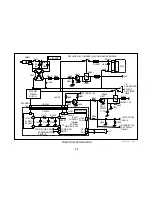
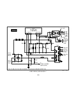
RY602 is closed when the set is turned ON. This applies AC to D605
Bridge Rectifier and R637. D605 Bridge Rectifier supplies DC to the switch-
ing supply through R626. R621 is added in order to keep excessive cur-
rent from being drawn by the switching supply at initial turn ON. R621 is
placed in series between the negative terminal of D605 Bridge Rectifier
and hot ground. This resistor is not in place in smaller sets that contain
R605 and R606. The negative terminal of D605 Bridge Rectifier is con-
nected directly to hot ground in these sets.
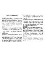
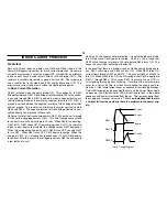
D606 is a thyristor that is connected across R621. When the set is turned
ON, 80 volts is developed across R621. This initial voltage causes D608
to conduct since its zener voltage is 20 volts. When D608 is conducting,
Q601 is ON. Q601 keeps C610 from charging when it is ON. As the initial
inrush current begins to dissipate, the voltage across R621 decreases.
When this voltage drops below 20 volts, D608 turns OFF, causing Q601
to turn OFF. When Q601 turns OFF, C610 begins to charge. When the
charge of C610, a 10-uf capacitor, reaches about 14 volts, D606 begins
to conduct. After this occurs, the voltage drop across R621 becomes only
a few tenths of a volt.
D603 is a 33 volt zener used for protection. It is not activated during initial
turn ON because C609 needs to charge. C609 is a 100-uf capacitor.
C609 will not charge to a level of 33 volts before D606 turns ON. This
keeps the circuit from activating at power ON.
In the event that there is a problem such as D606 opening during opera-
tion, C609 will charge and D603 will turn ON. When D603 turns ON,
current flows through D607 and R619. This causes Q602 and Q603 to
turn ON. When Q603 turns ON, the VIN voltage from C620 is applied to
IC601/1 through R644. This causes IC601 to activate its own OCP cir-
cuit, stopping the supply from switching. If a failure of this nature were to
occur for a very short time, less than four seconds, the supply could re-
start itself. If the failure lasted longer, a sequence of four flashing Standby/
Timer LED followed by a pause would occur and the Power Relay would
be opened. The Standby/Timer LED will continue to flash in the above
sequence until power is removed from the set. This removes power from
the supply and it ceases to function.
This is an indication that there is
a vertical failure when actually there is a problem in the power sup-
ply.
Содержание FD TRINITRON WEGA KV-13FM12
Страница 27: ...22 NOTES ...
Страница 48: ...APPENDIX ...

