19
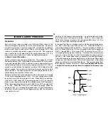
will repeat. Every time this cycle repeats, a chirping sound can be heard
from the power supply. This chirp occurs when the VIN voltage rises
again to a voltage at which IC601 can operate. This chirping sound is
made each time the supply begins to restart. It will continue to repeat
until the Syscon IC senses a vertical failure. At that time the power relay
will be turned OFF and the Standby/Timer LED will flash in sequences of
four.
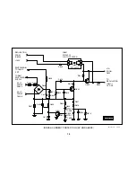
An example of this failure would be a short on the 135-volt
line such as VM Output short. This type of failure would not
be associated with a Horizontal failure such as H Out, 200-
volt short (Video Amp) or FBT. That circuit contains another
OCP that would cause the Standby Timer LED to flash in
sequences of two. This will be discussed later.
Thermal
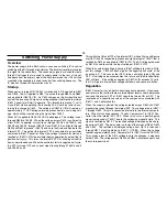
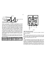
The thermal shutdown works by sensing the temperature of the lead frame
that the IC is mounted to internally. The semiconductor wafer is mounted
to a lead frame to dissipate heat. When the temperature of the frame
reaches 140 degrees Celsius, the latch is activated. Power must be dis-
connected for operation to restart.
Operating the Supply without a Load
It is important to be able to isolate whether a problem is in the power
supply or other circuitry. This supply can be run unloaded at AC input
voltages ranging from 30VAC to 120VAC.
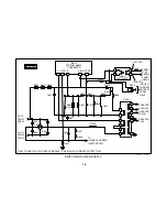
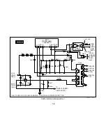
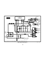
You can unload the supply by unsoldering one side or removing L603.
After removing L603, place a jumper across the contacts of RY602. Plug
the set into a variac and begin to slowly bring up the AC voltage. At about
30 volts, the supply will begin to operate. The following table shows the
state of several points at various AC input voltages:
IC601/1
IC601/3
IC601/4
Switching B+
40VAC
.87 VDC
160 Vpp
12 VDC
51 VDC
60VAC
.98 VDC
200 Vpp
12.83 VDC
79 VDC
80VAC
1.11 VDC
230 Vpp
13.2 VDC
106 VDC
100VAC
1.21 VDC
260 Vpp
13.5 VDC
134 VDC
120VAC
1.22 VDC
280 Vpp
13.9 VDC
163 VDC
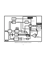
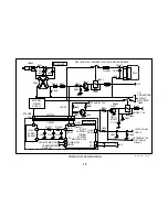
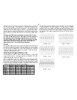
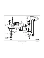
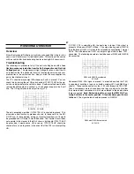
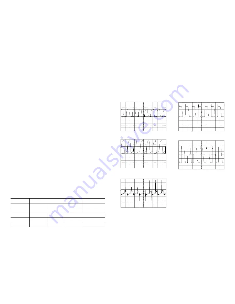
IC601/2 1v 5us
IC601/1 1v 5us
D614/K 2v 5us
T603/7 10v 5us
IC601/3 100v 5us
You should also note that under the above conditions the +135 volt output
at L603 remained at 136 volts throughout. The signal seen at IC603/3
started as sine waves clipped at the negative peaks and gradually came
to look more like a normal sine wave as the input voltage was increased.
The frequency of this signal ranged from 236 kHz at 40 VAC to 320 kHz at
120 VAC.
Содержание FD TRINITRON WEGA KV-13FM12
Страница 27: ...22 NOTES ...
Страница 48: ...APPENDIX ...

